How I build the show

On my workbench · In progress

A drum that plays the lights

I went to Woodland Park Zoo for the holiday lights and came home with a project. I wanted to try one of the effects in my own yard, so with some help from AI, I’m building a drum that lets kids play the lights.

Inside the drum

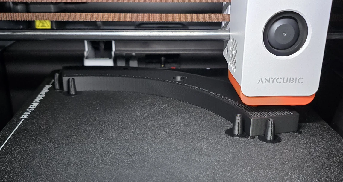
I started with a real 12-inch drumhead. The drum was too wide for my 3D printer, so I printed the rim, bowl, and base a quarter at a time.

Under the head, a little piezoelectric disc turns a tap into an electrical pulse. I soldered a circuit so the controllers can pick up the beat. One flashes the drumhead. The other sends a trail of color racing across the yard.

The tricky part? The head keeps vibrating after your hand comes off. I’m tuning it so one tap counts as one beat.

How do you print a drum this big?

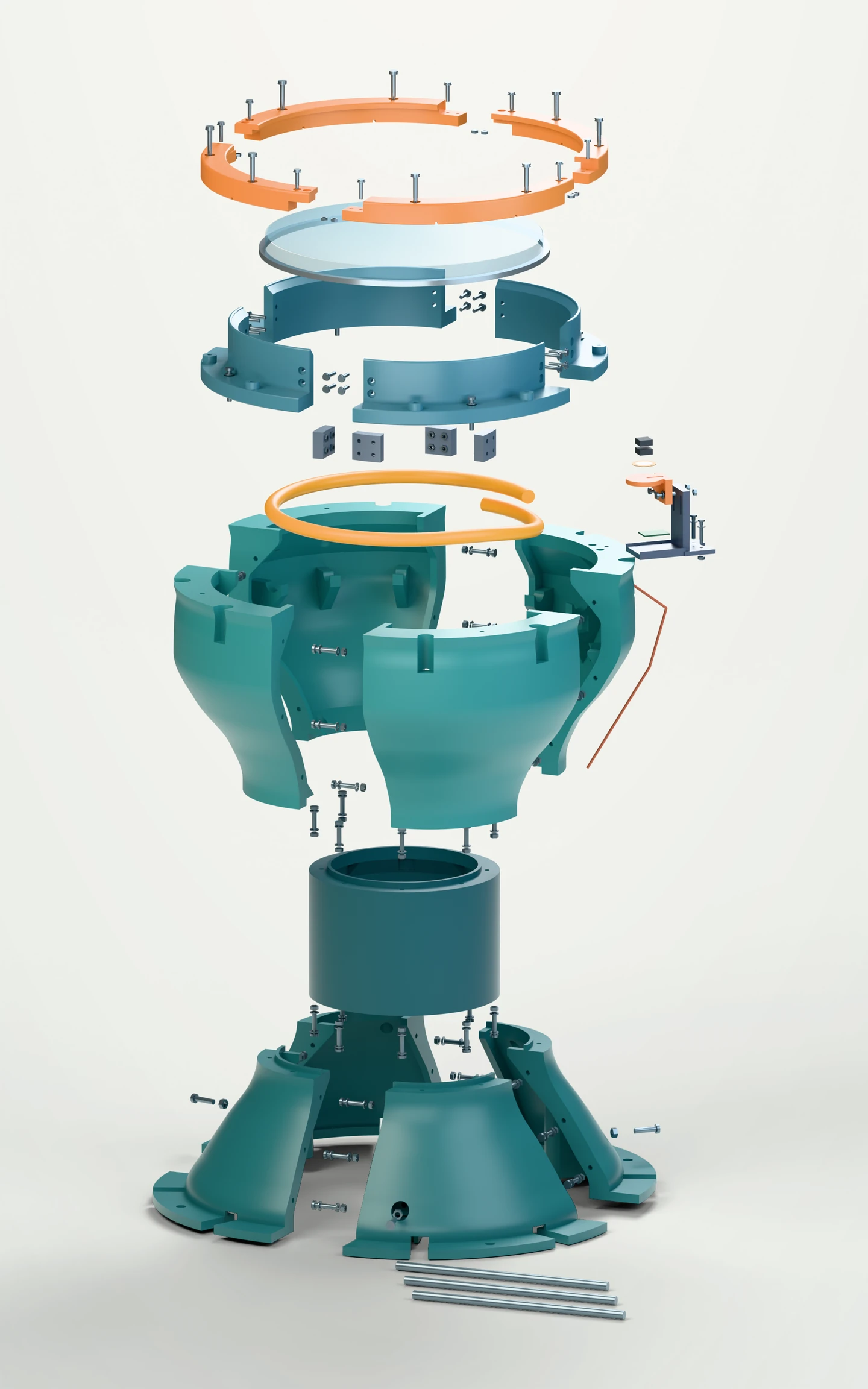
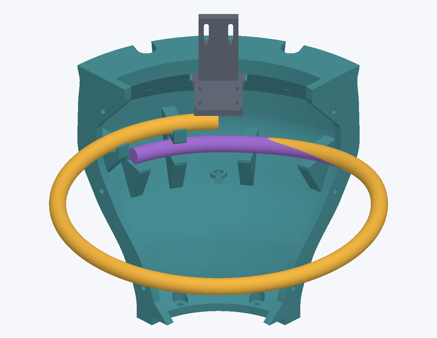
A hollow neck bolts the bowl to the flared foot. Little shelves inside the bowl hold a loop of LED rope just under the clear head.

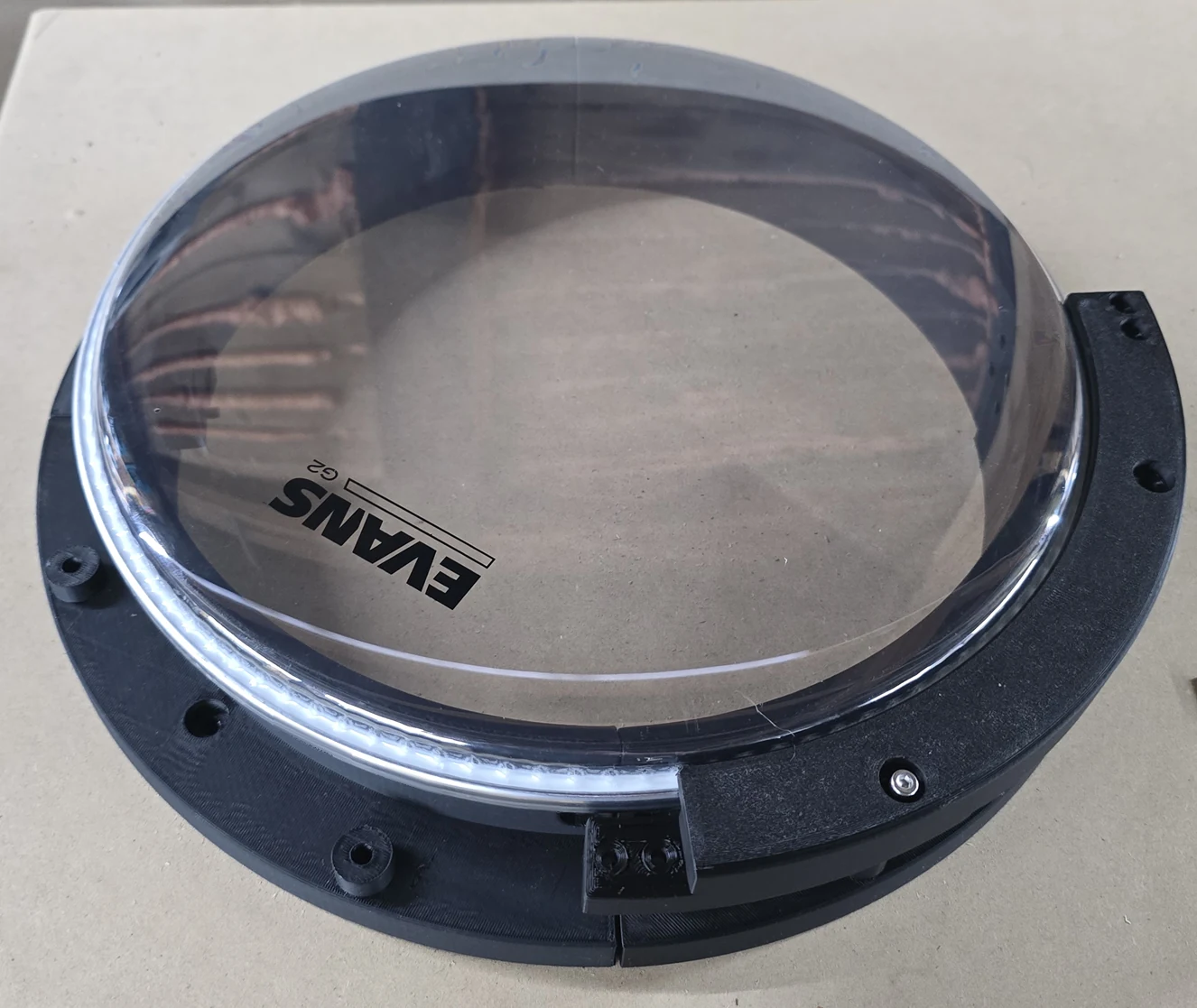
Clear Evans drumhead resting in the curved black rim on the bench.
The clear drumhead in the rim I printed for it.
Cutaway CAD model with a yellow loop of light supported on ledges inside the upper bowl.
In the model, the yellow line is the rope light. Its tail tucks under the start of the loop.
The print head above black curved parts on the printer bed.
The rim starts as curved pieces on the print bed.
What can feel a tap?

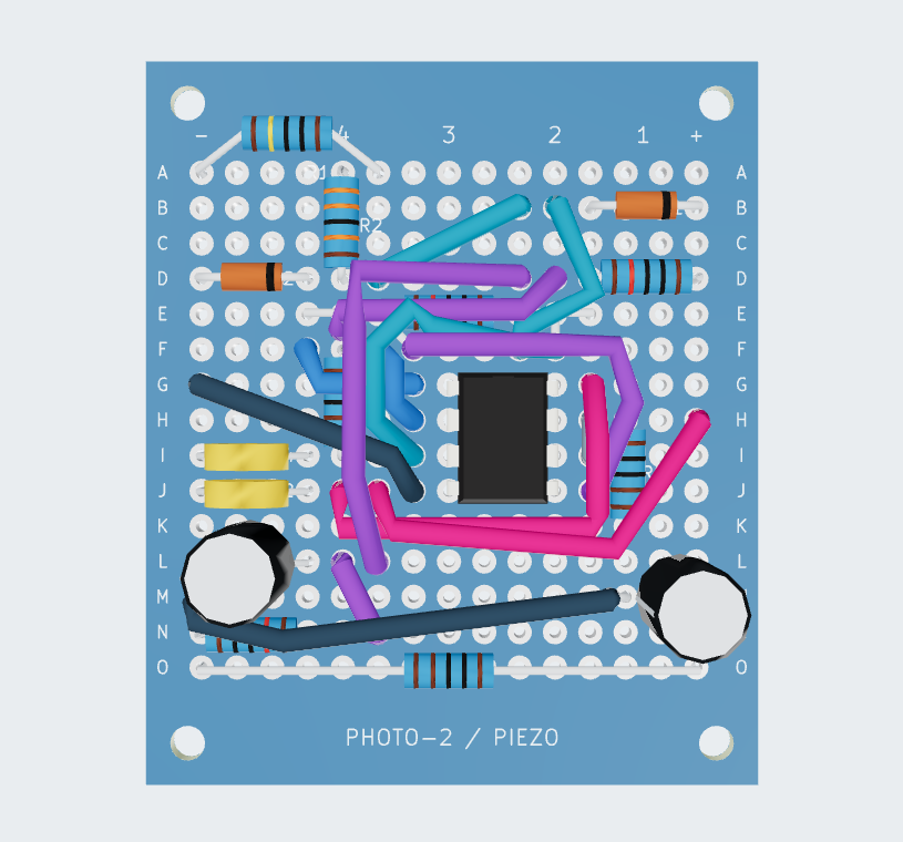
The circuit brings the disc’s pulse into a range the drum controller can read. I used the layout I drew in KiCad as a guide for soldering the board.

Top view of the circuit board model, showing the chip, components and colored wire paths.
My board layout in KiCad. I can follow each colored wire from hole to hole.
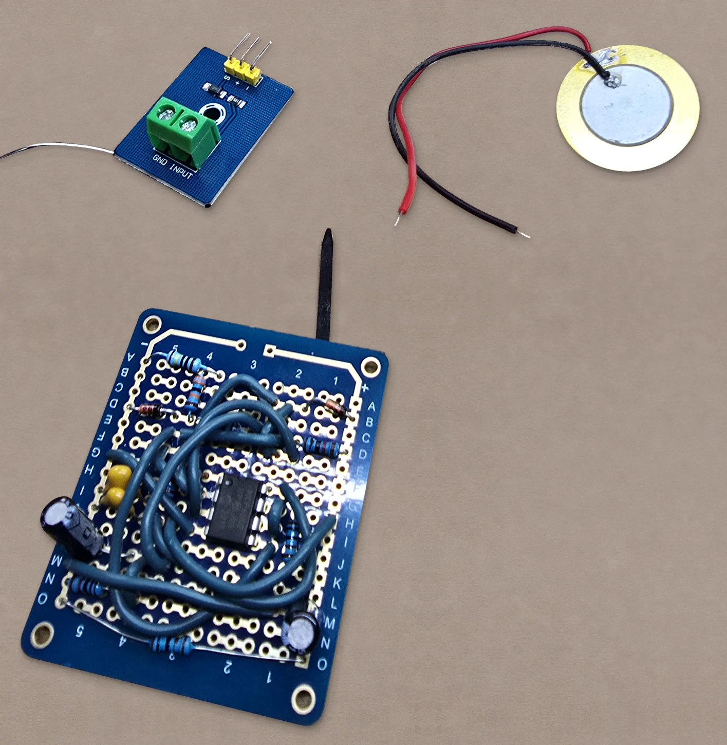
The brass pickup disc, blue input board and hand-soldered circuit with dark wire loops.
The brass disc feels the tap. The larger blue board is the circuit I soldered.
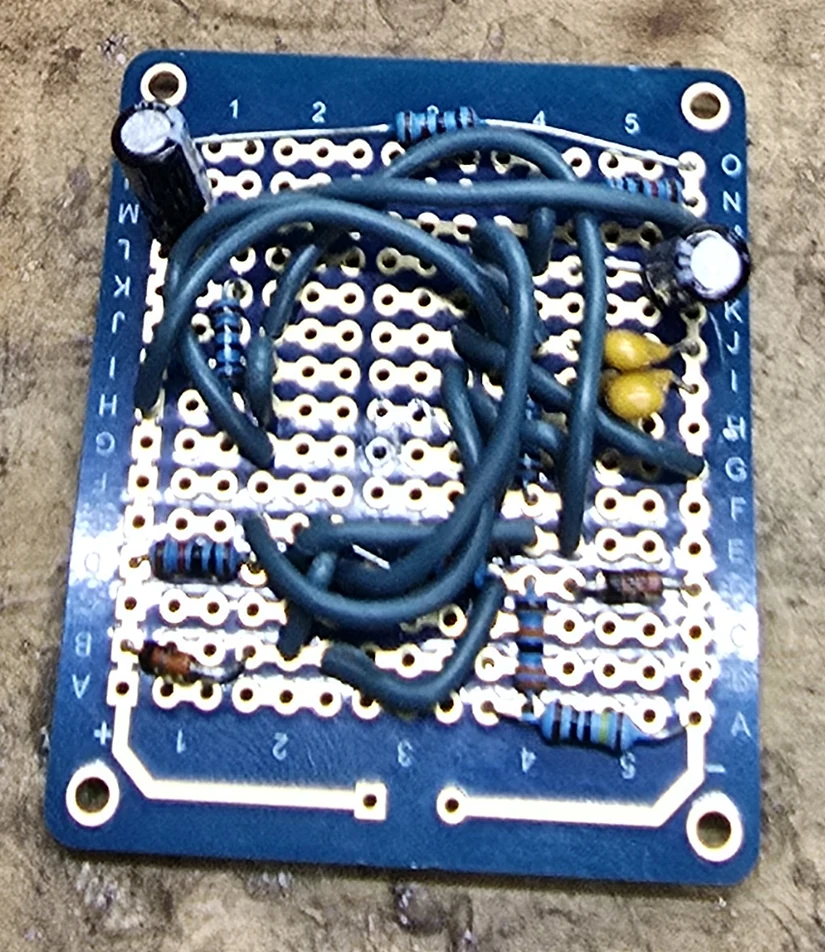
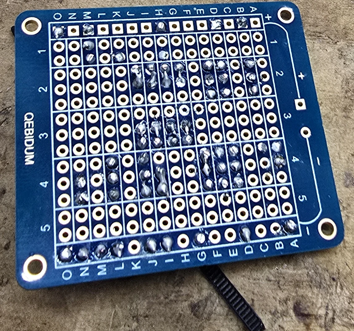
Three stages of soldering
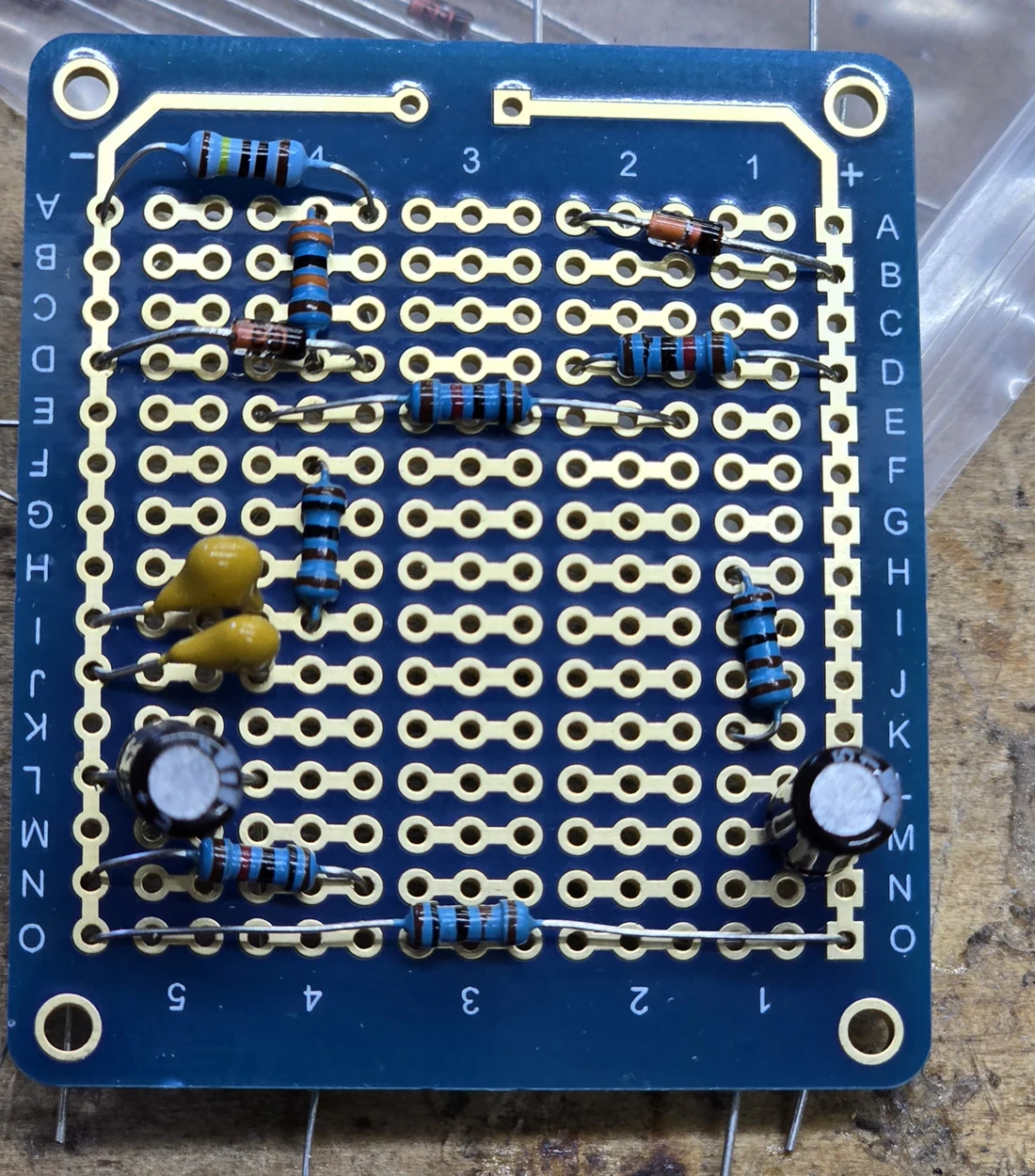
Small components soldered into a blue board before the crossing wires are fitted.
I start with the small components.
Short insulated wires looping across the component side of the board.
Short wires make the connections on top.
The underside of the blue board with shiny solder joints.
The same board turned over to show the solder joints.
What happens when I tap the drum?

On the bench, I’ve seen a gentle tap register and a hit reach the show controller. The drum’s ESP32 flashes the light under the head red, green, then blue on successive taps. It fades to a soft blue between hits.

A wire carries the beat to the Dig-Uno. Six strands share one output and four share the other. The color runs along one strand at a time. Each starts back near the drum, so the next one takes the color in a new direction. Another tap can start a second chase while the first is still moving.

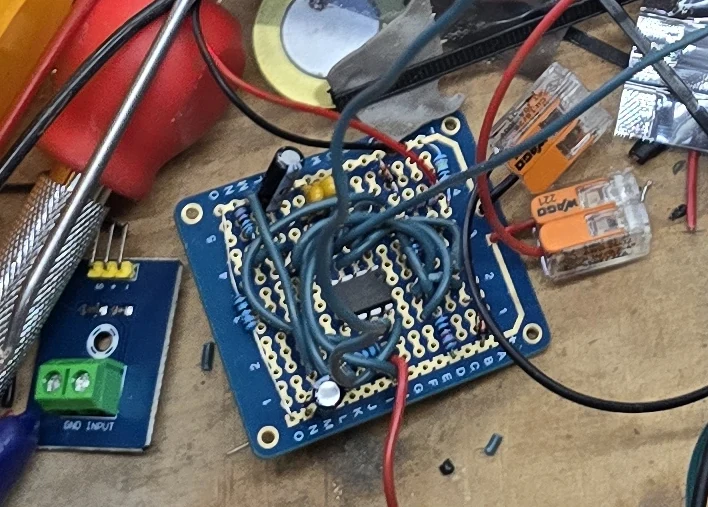
The brass pickup disc and test leads above the hand-wired blue circuit board.
With the disc out on the bench, I can try a gentle tap while I tune the software.
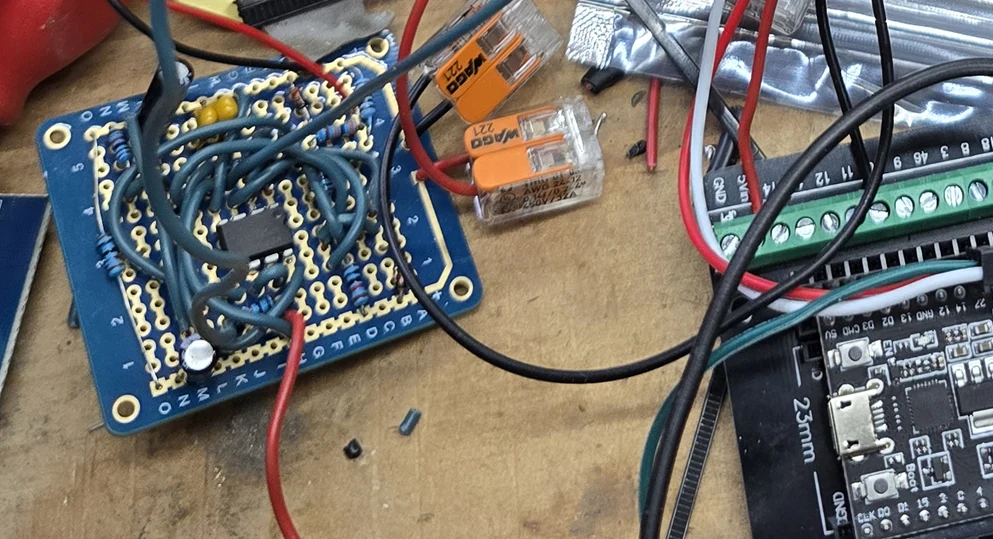
The soldered board on the workbench connected with leads for a sensor test.
The leads carry the signal from my board on the left to the drum controller on the right.

More from the workshop

The big screen and the little FM sign

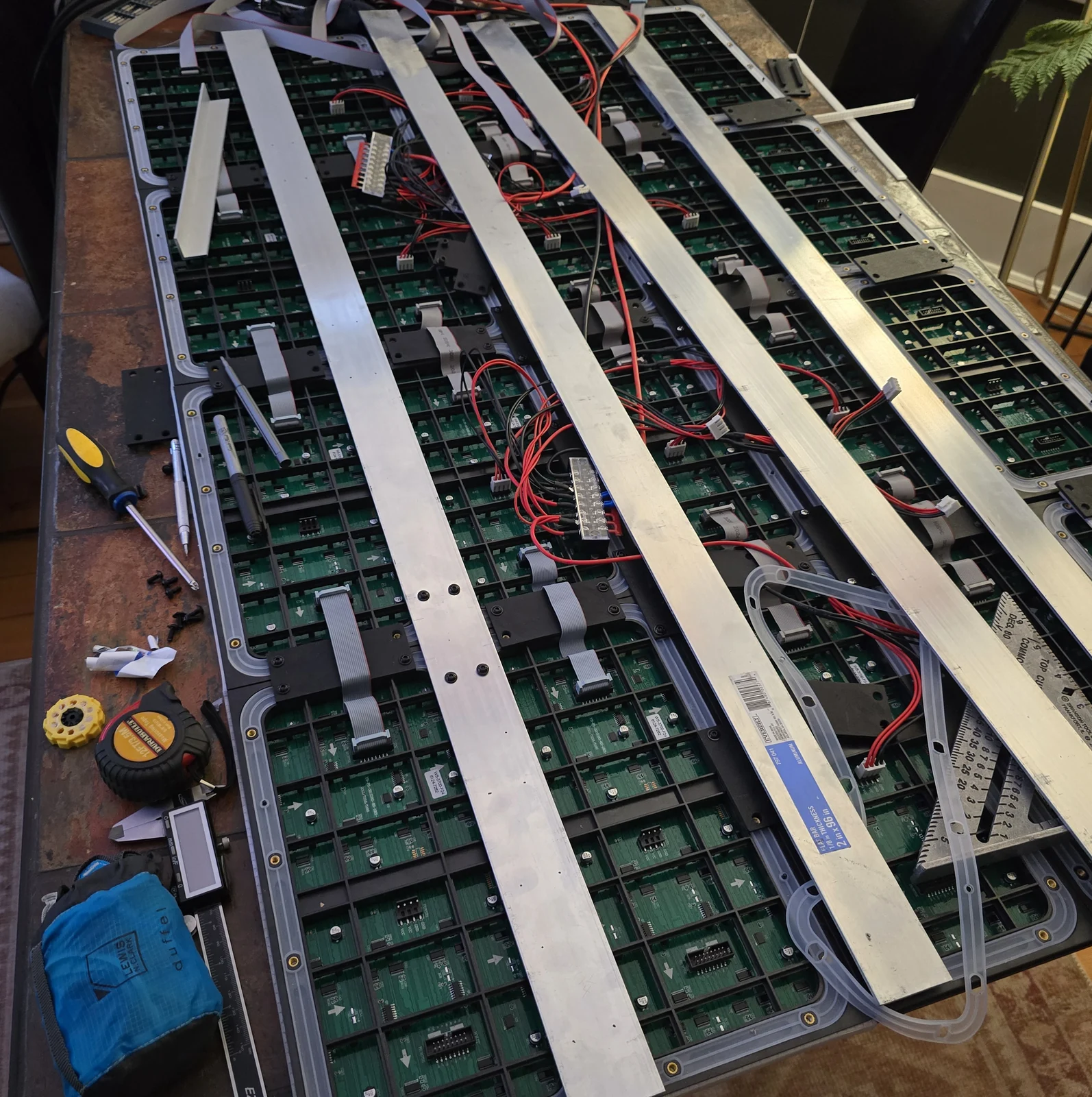
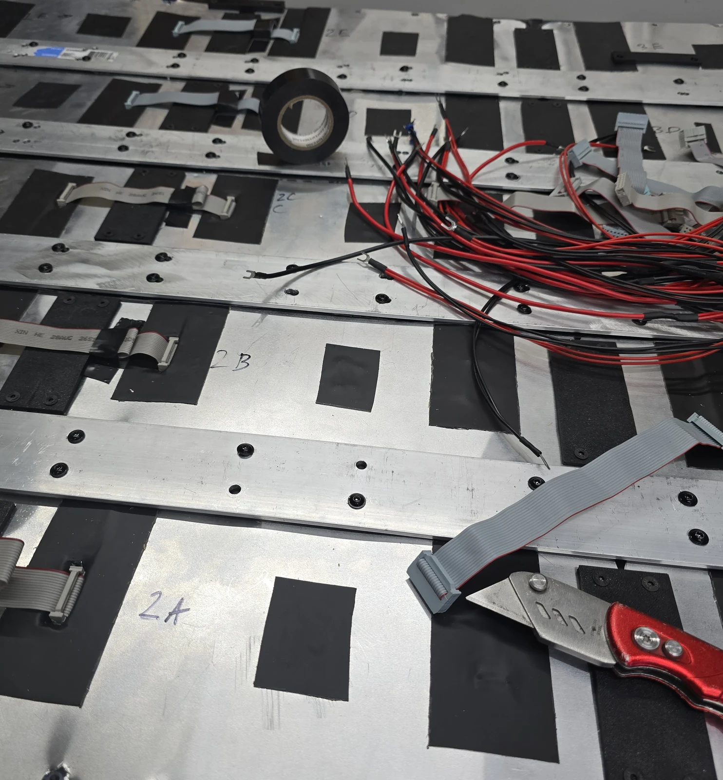
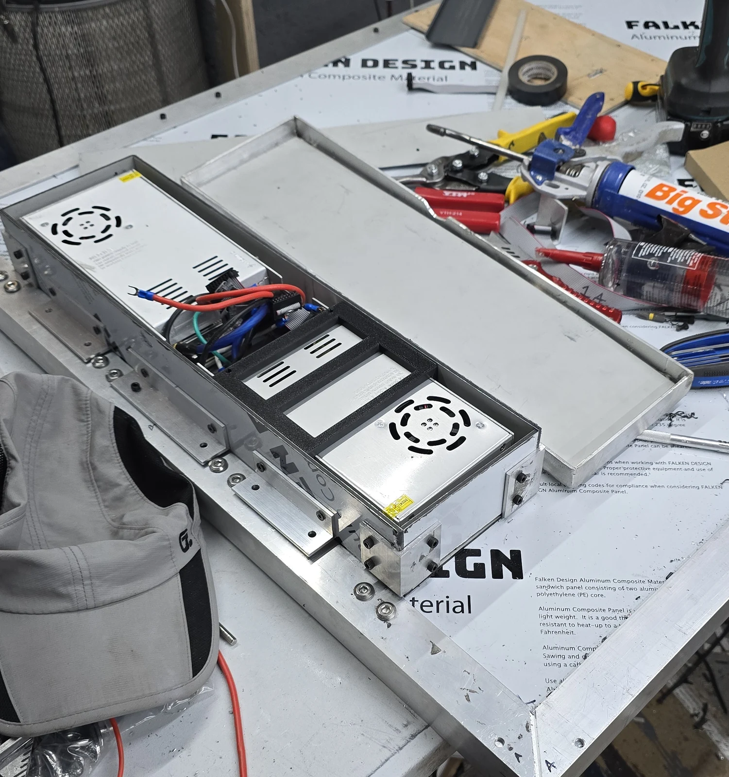
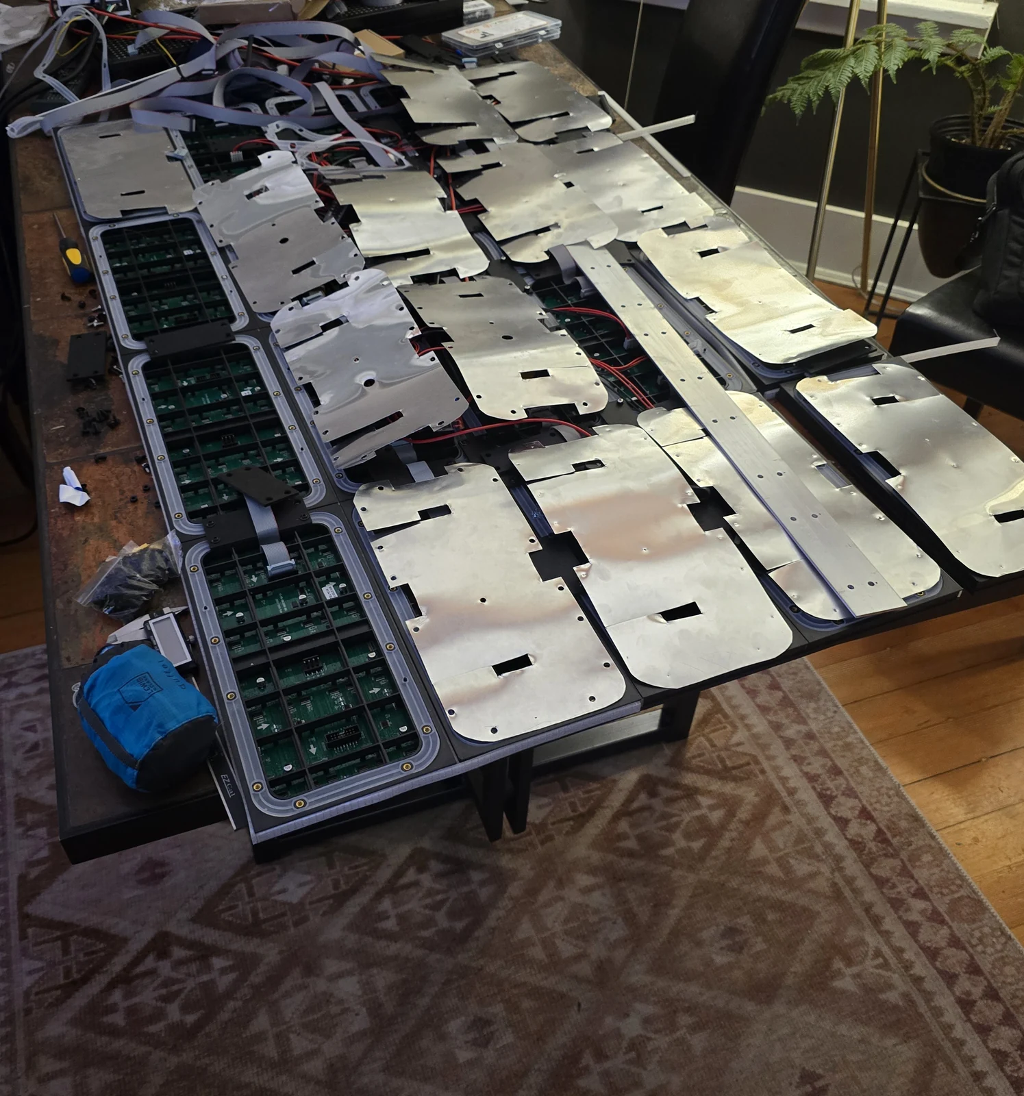
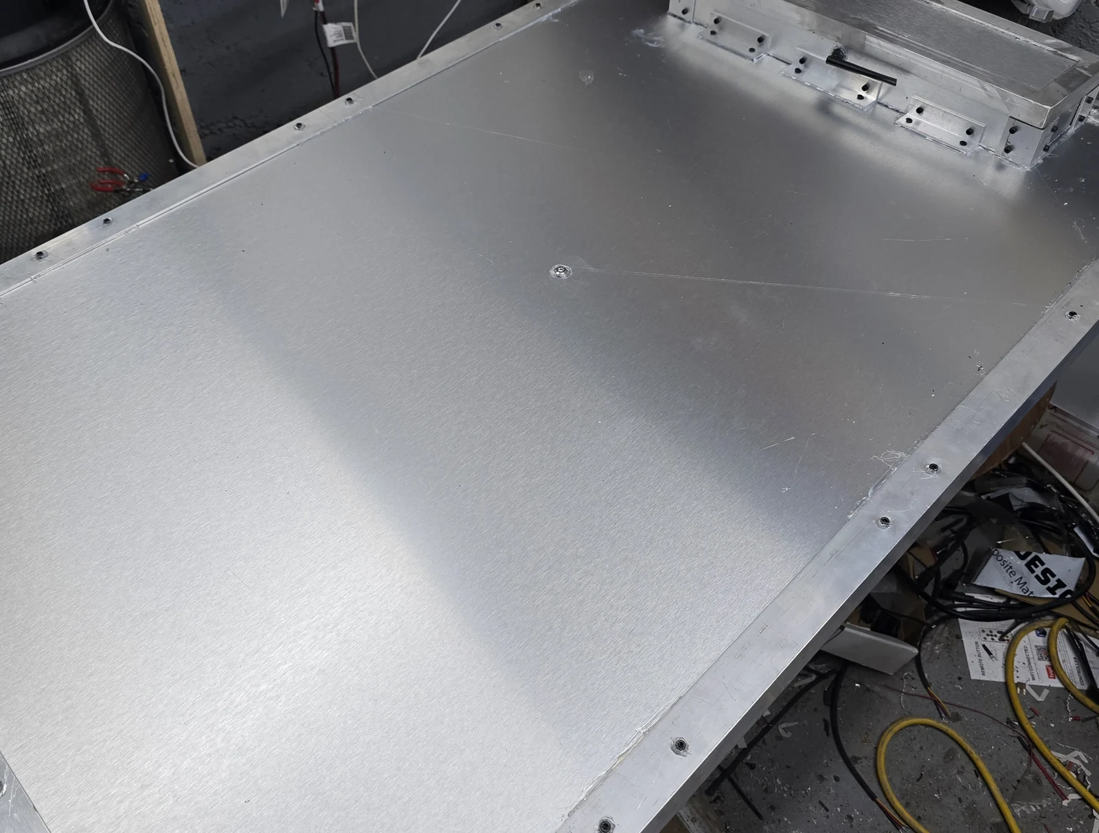
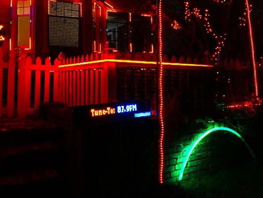
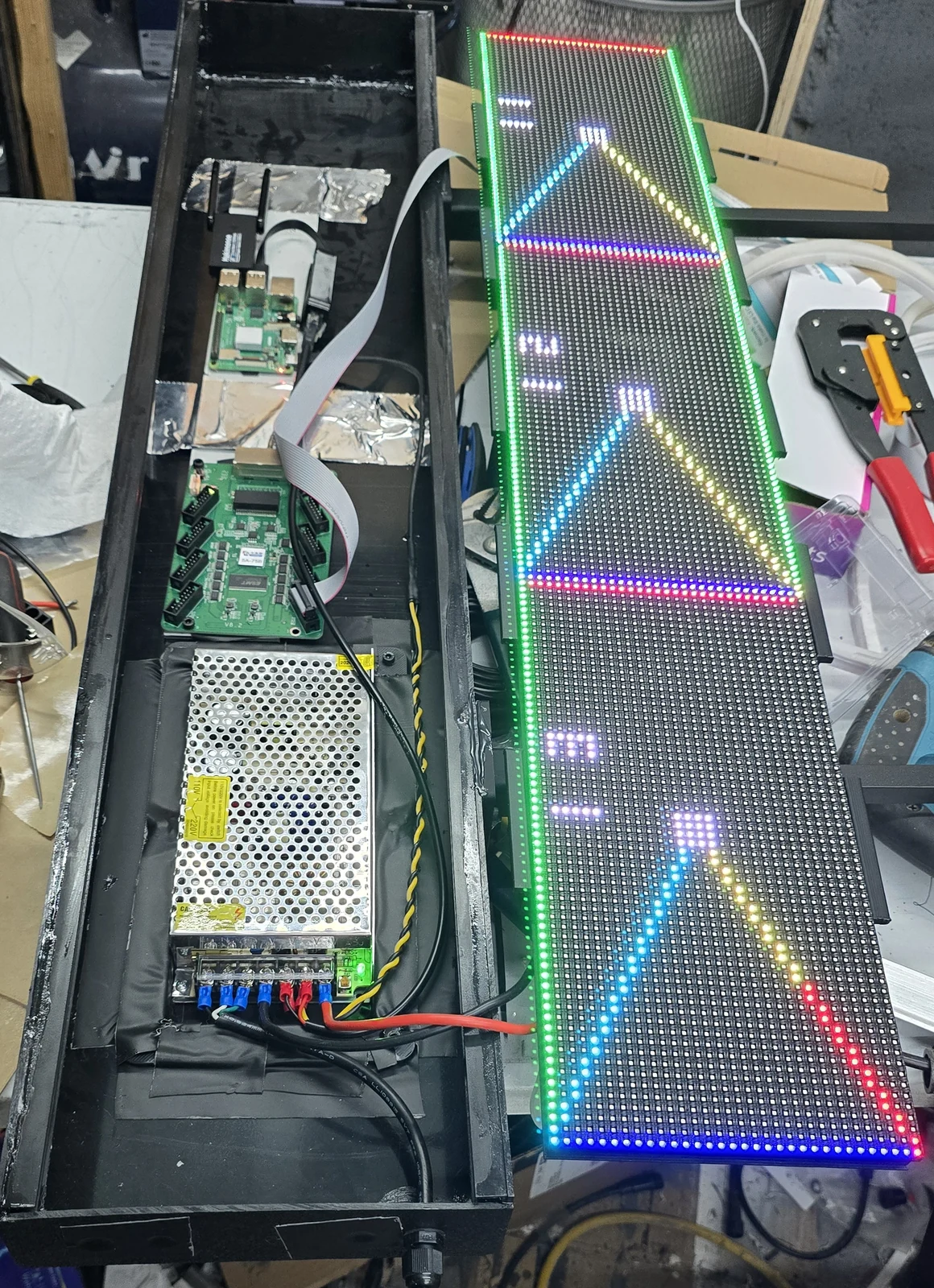
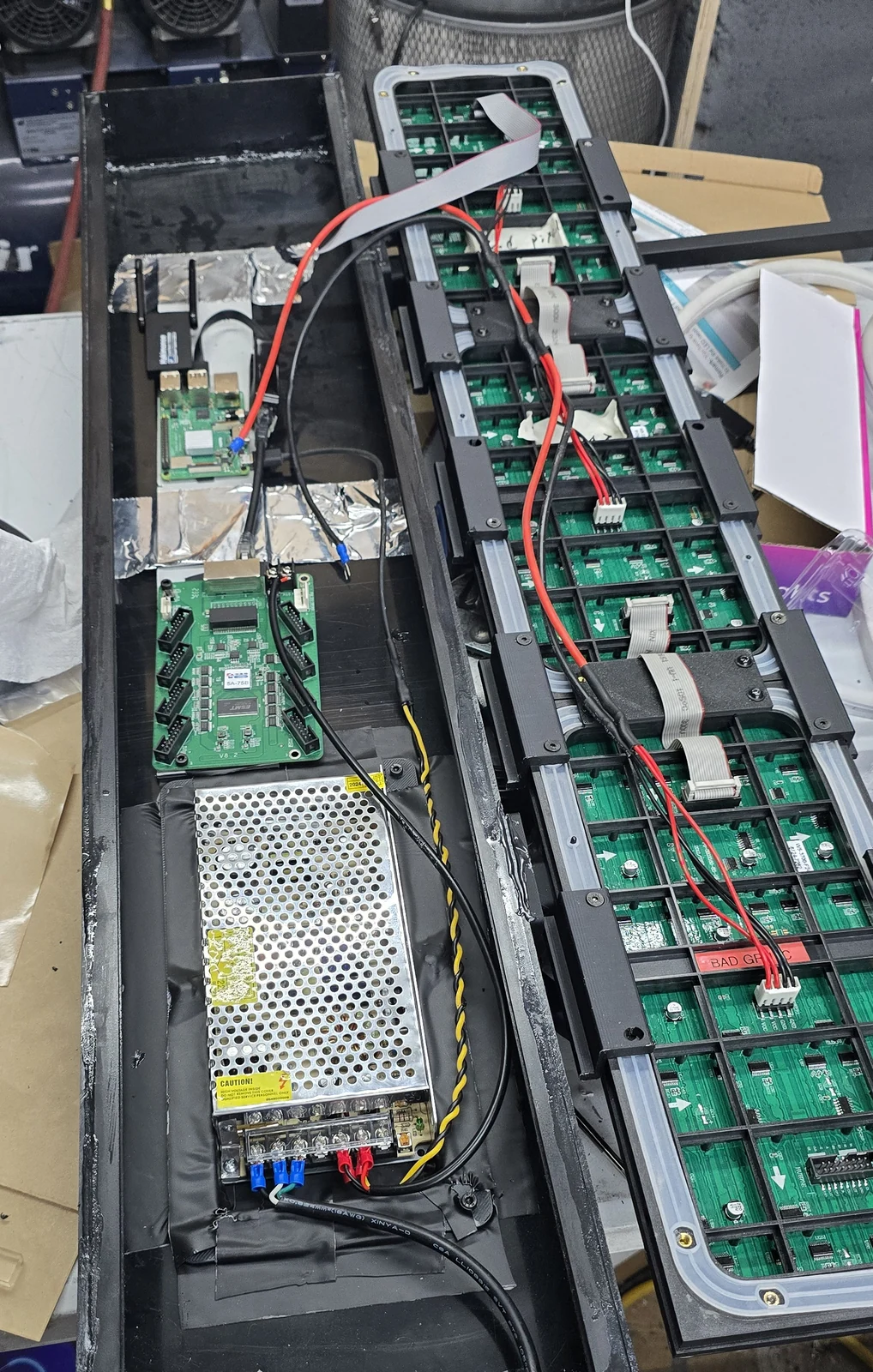
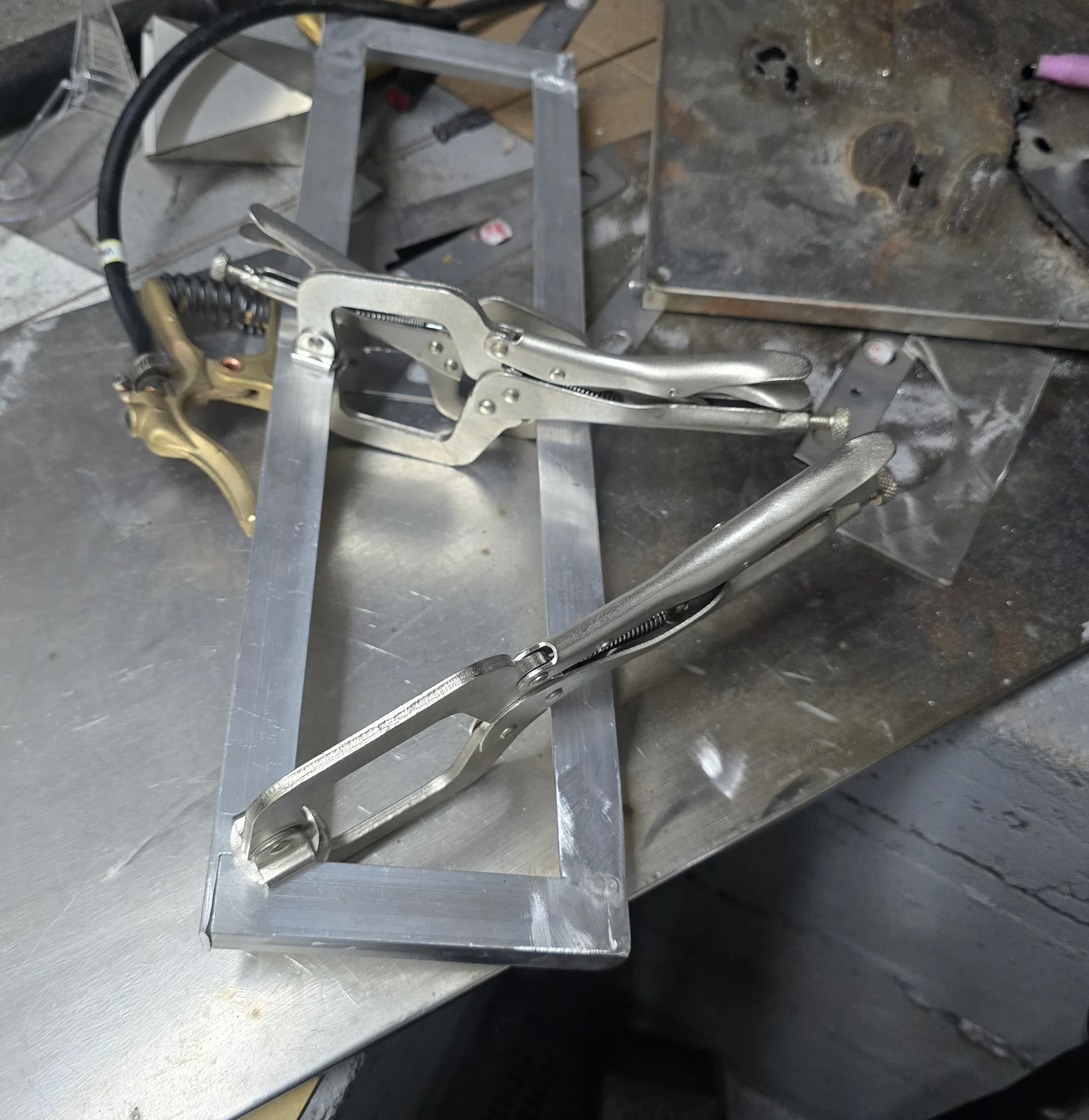
The big screen out front and the little 87.9 FM sign by the steps use the same LED panels. For the big screen, I wired a grid of them together in an aluminum frame so one picture stretches across them all. For the sign, I had an old aquarium light housing lying around. Three panels fit inside once I printed brackets to hold them.
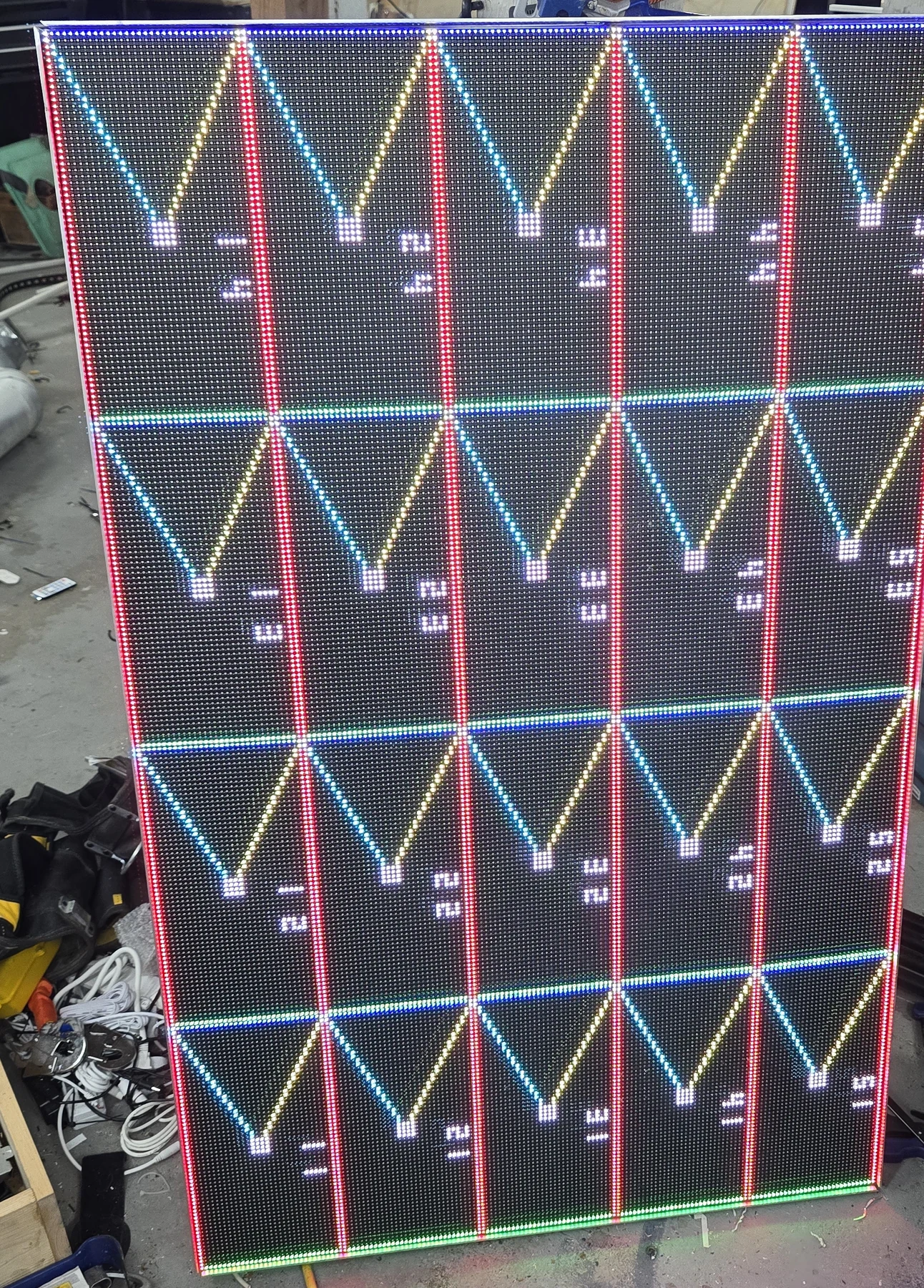
These are called P5 panels because their lights sit five millimeters apart, measured from center to center.

I got most of the frame materials at Home Depot and ordered the panels from AliExpress. The aluminum cover goes on last, with cutouts for the cables.

Tune-to sign

I sealed the case and printed one more bracket to hang it on the post. A Raspberry Pi 4 and a Colorlight card run the sign.

See the printed sign bracket
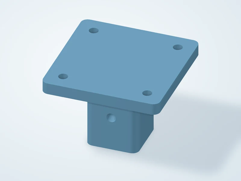
  • Square plate with four corner holes on top of a post sleeve with a side hole.
    Tune-to Sign Post Bracket

    The flat plate goes against the sign, and the sleeve fits the post.

How the lights learn a song

How the lights learn a song

Once I’ve mixed a song, I get to decide what a beat looks like in the yard. In xLights, I can send it sweeping across all three arches. The singing faces take a little more fiddling. I match the mouth shapes to the sounds in each word, then nudge the timing by hand until the face looks like it knows the words.

The Halloween mashup

  1. Stranger Things
  2. Seven Nation Army
  3. Ghostbusters
  4. Thriller
Put the songs together FL Studio

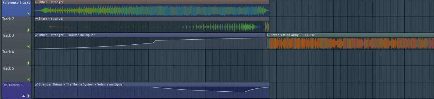
I use FL Studio to put together mashups and make my own cuts of songs for the show.

Audio clips from the Halloween mashup arranged in the FL Studio Playlist.
The Halloween mashup in the FL Studio Playlist.
Mark the sounds I want to use SpectraLayers Pro

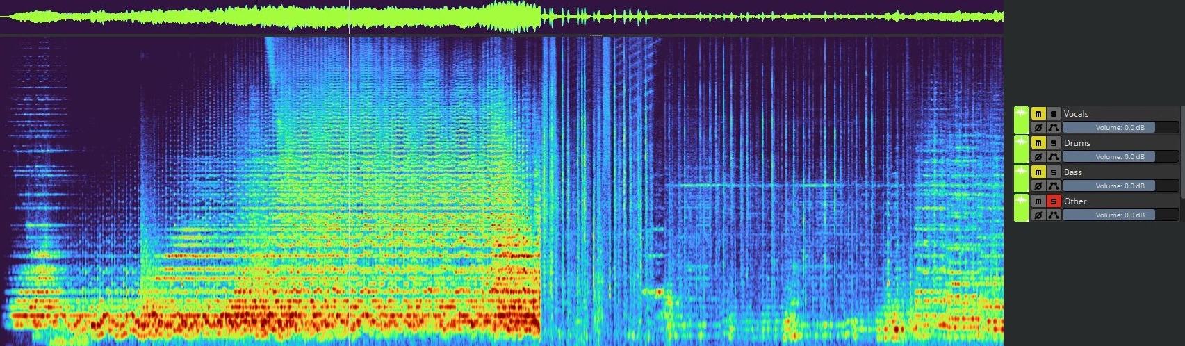
Once the track is ready, I use SpectraLayers to add timing marks for the lights.

The saved mashup’s waveform and colored spectrogram alongside its vocals, drums, bass, and other layers.
The layers on the right let me listen to one part of the mix at a time.
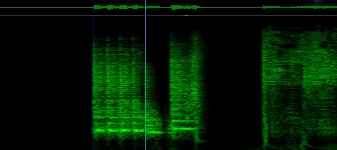
Two blue timing lines over the isolated cymbal spectrogram. The first line sits at the start of a bright green cymbal hit.
The blue lines mark where the cymbal hits start.
Turn timing marks into lights xLights

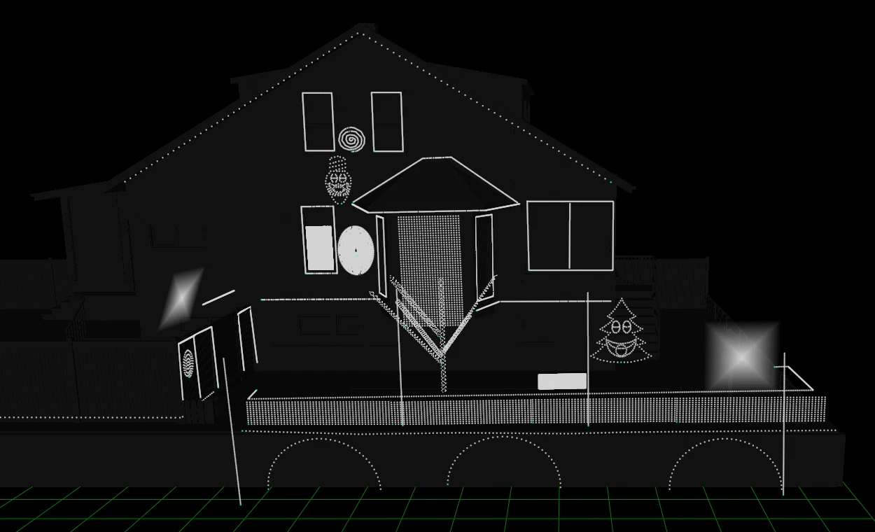
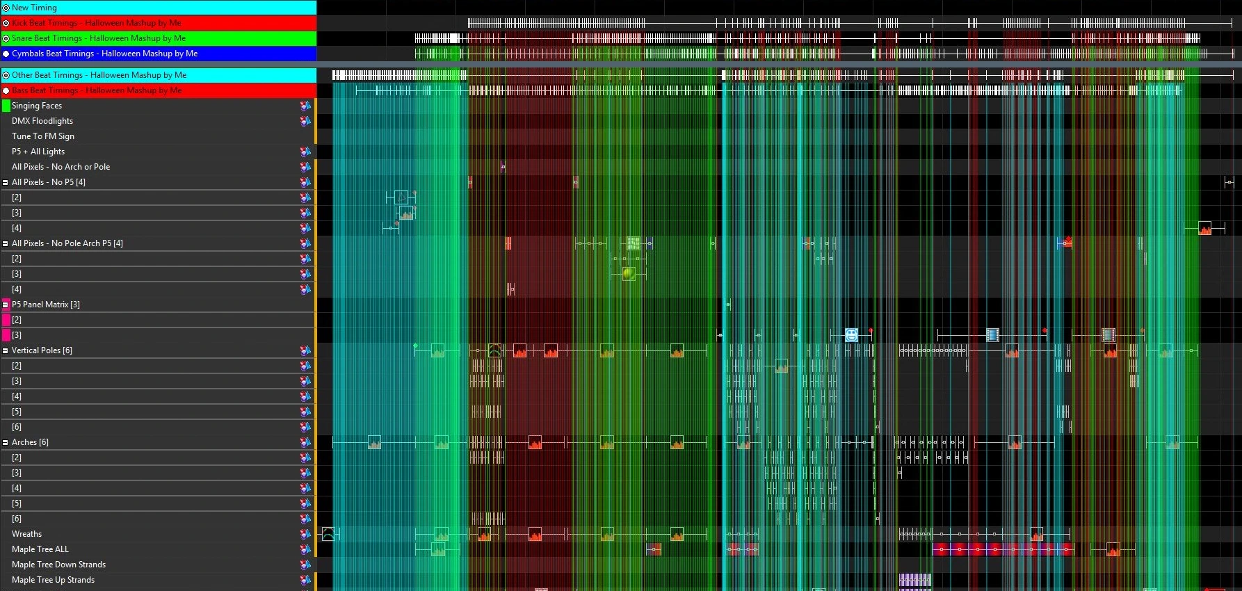
All the props get mapped onto a 3D model of the house in xLights. That lets me see how they'll look together while I time the lights to the music. Each prop or group has a row in the Sequencer, where I add effects and line them up with the sounds I marked earlier.

An online tool breaks the vocal track into sounds and marks when each one starts. Those marks give me a starting point for timing the singing faces.

3D house layout
The house in xLights, with three arches along the front, four upright poles, and strands on the maple tree.
Sequencer Arches
The Halloween mashup in xLights. Colored timing tracks sit above rows of effects for each prop group.

I group the three arches so I can send a sweep of light across all of them.

Ask me about sequencing
Inside the control boxes

Inside the control boxes

If I’ve got a loose wire, I want to find it while it’s still on my workbench. That’s where I solder and test the connections. Once the boxes go out in the yard, they have two jobs. They power the props and tell each light when to change color.

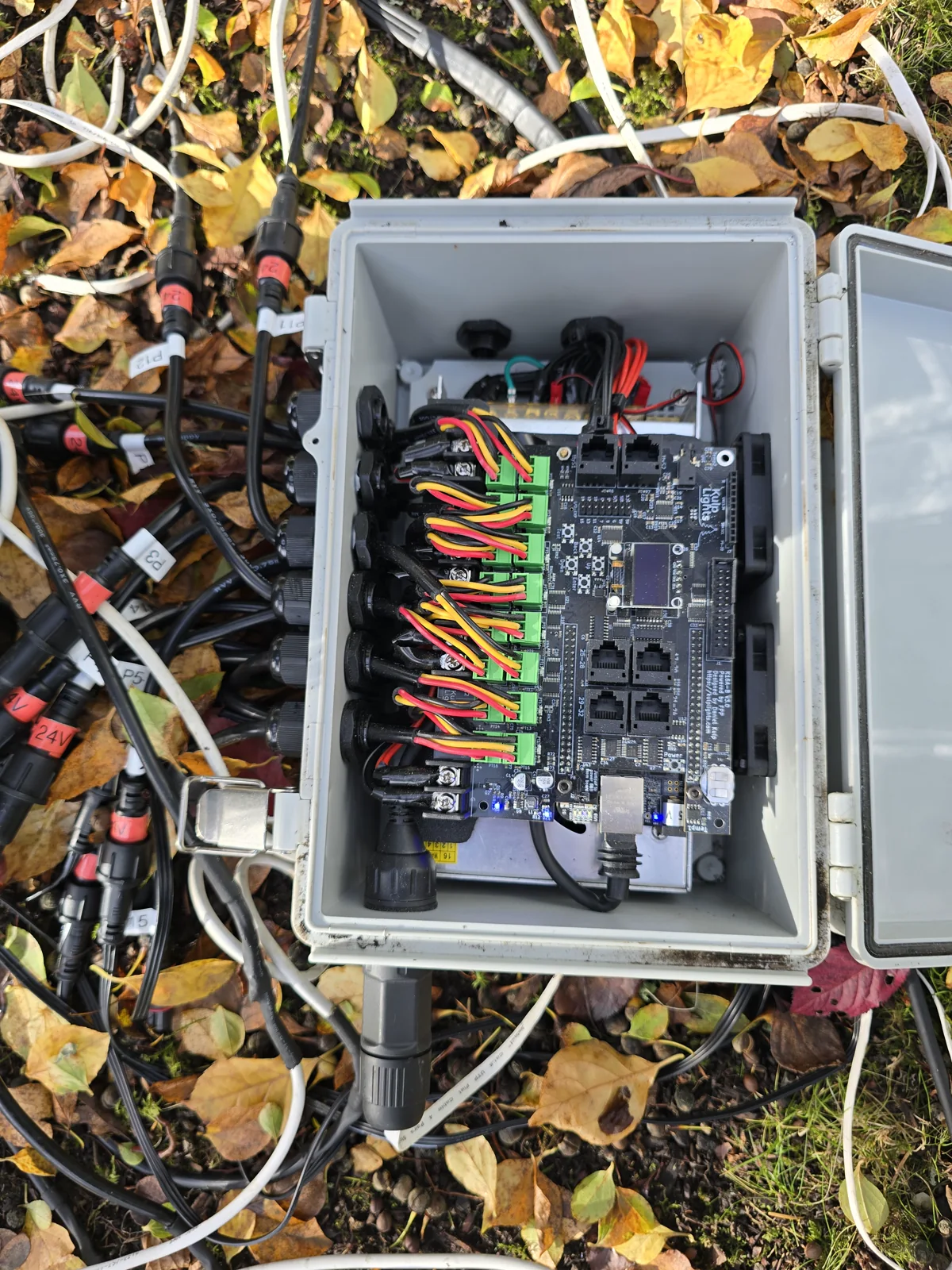
An open gray enclosure in the yard holds a Kulp controller board with rows of wired green terminals.
A controller box in the yard. Each connection goes out to part of the display.
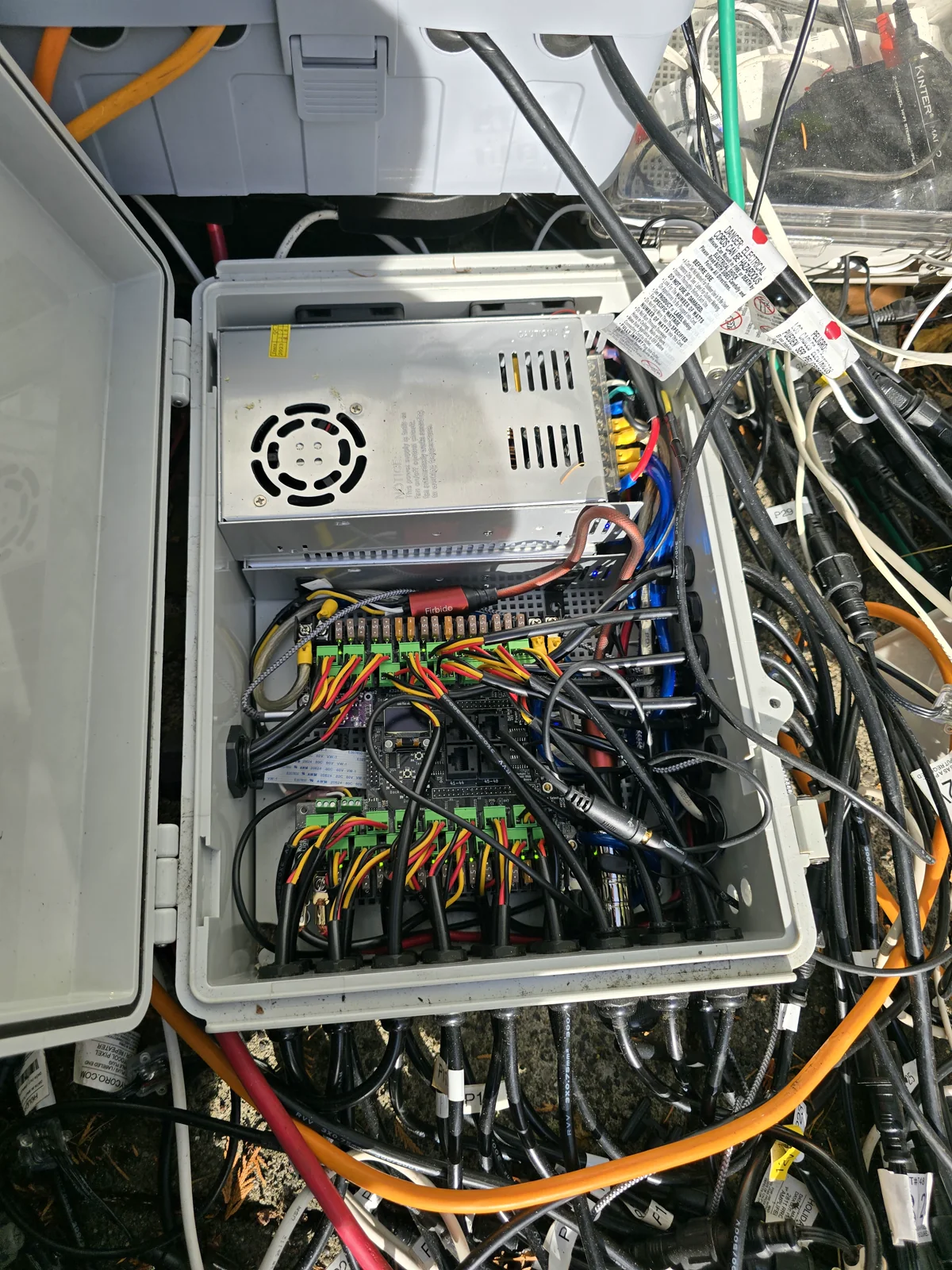
A large power supply sits above a wired controller board inside an open outdoor enclosure.
Another box, with the power supply above the controller and cables leaving through the sides.
Networking, audio, and a closer look at the wiring
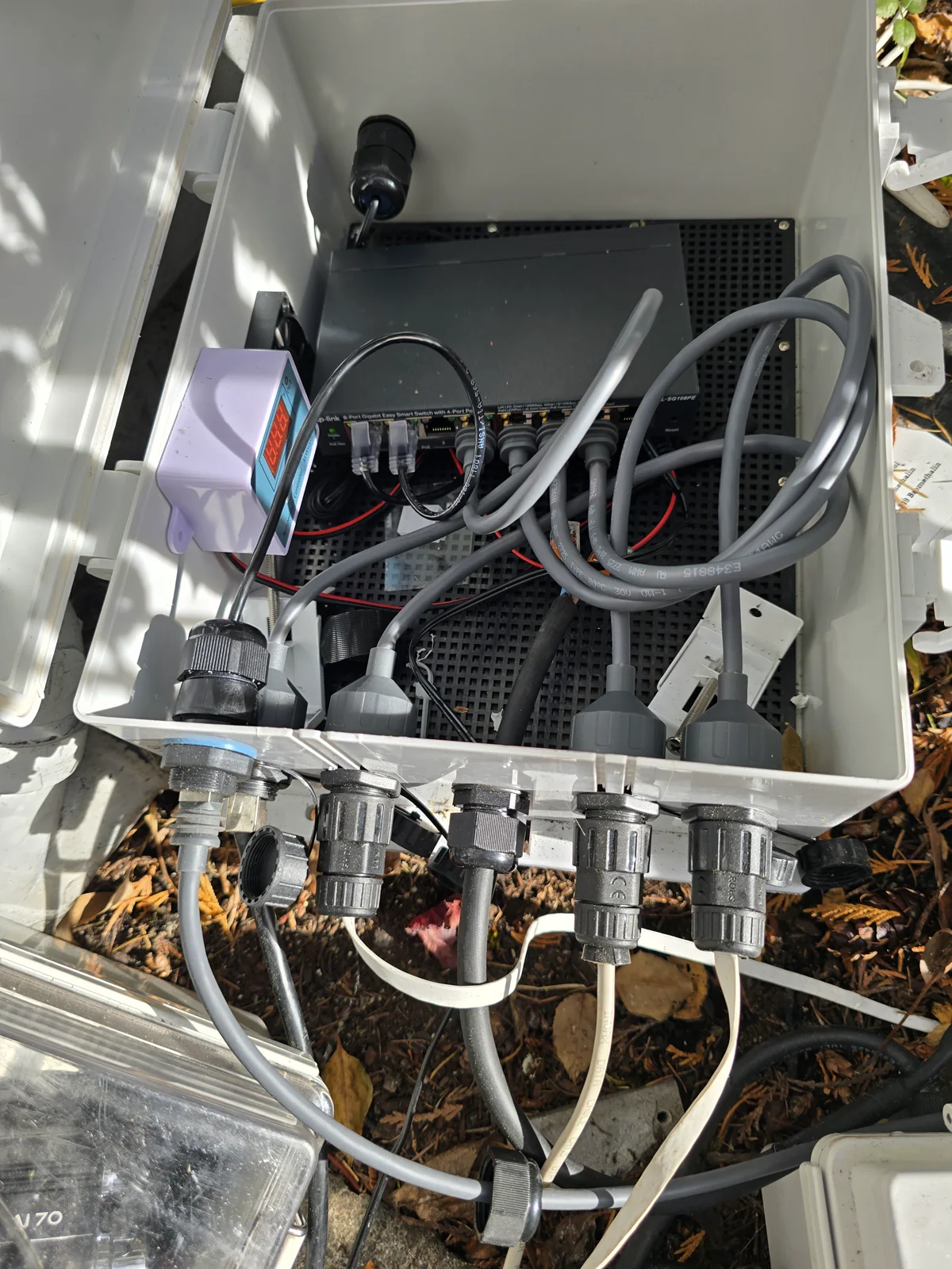
A network switch and Ethernet cables inside a gray enclosure with cable fittings along the bottom.
The show network has its own enclosure.
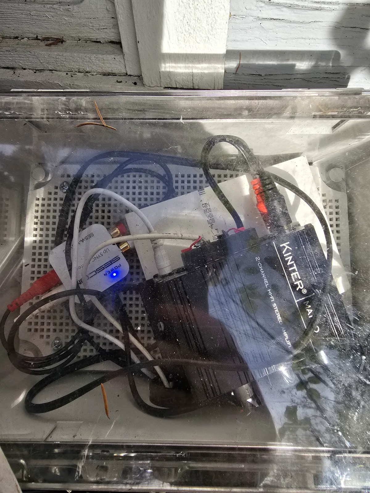
An audio amplifier and connected cables behind the clear cover of an outdoor box.
The audio hardware, seen through the clear cover.
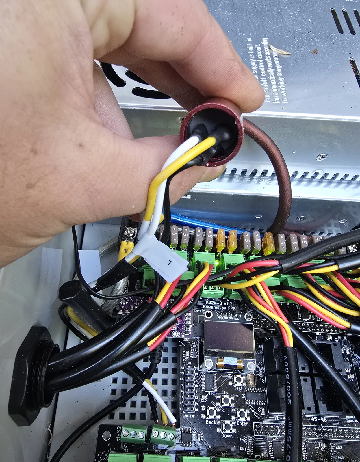
A hand holds the back of a round connector above the wiring in an open enclosure.
One of the connectors I wired for an earlier build.
How the props stay up
How the props stay up
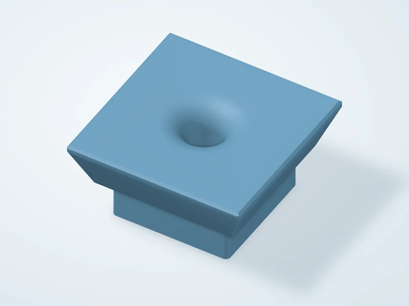
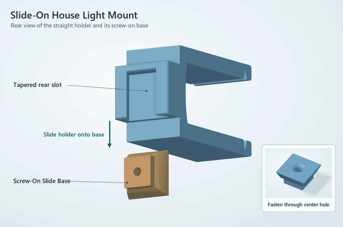
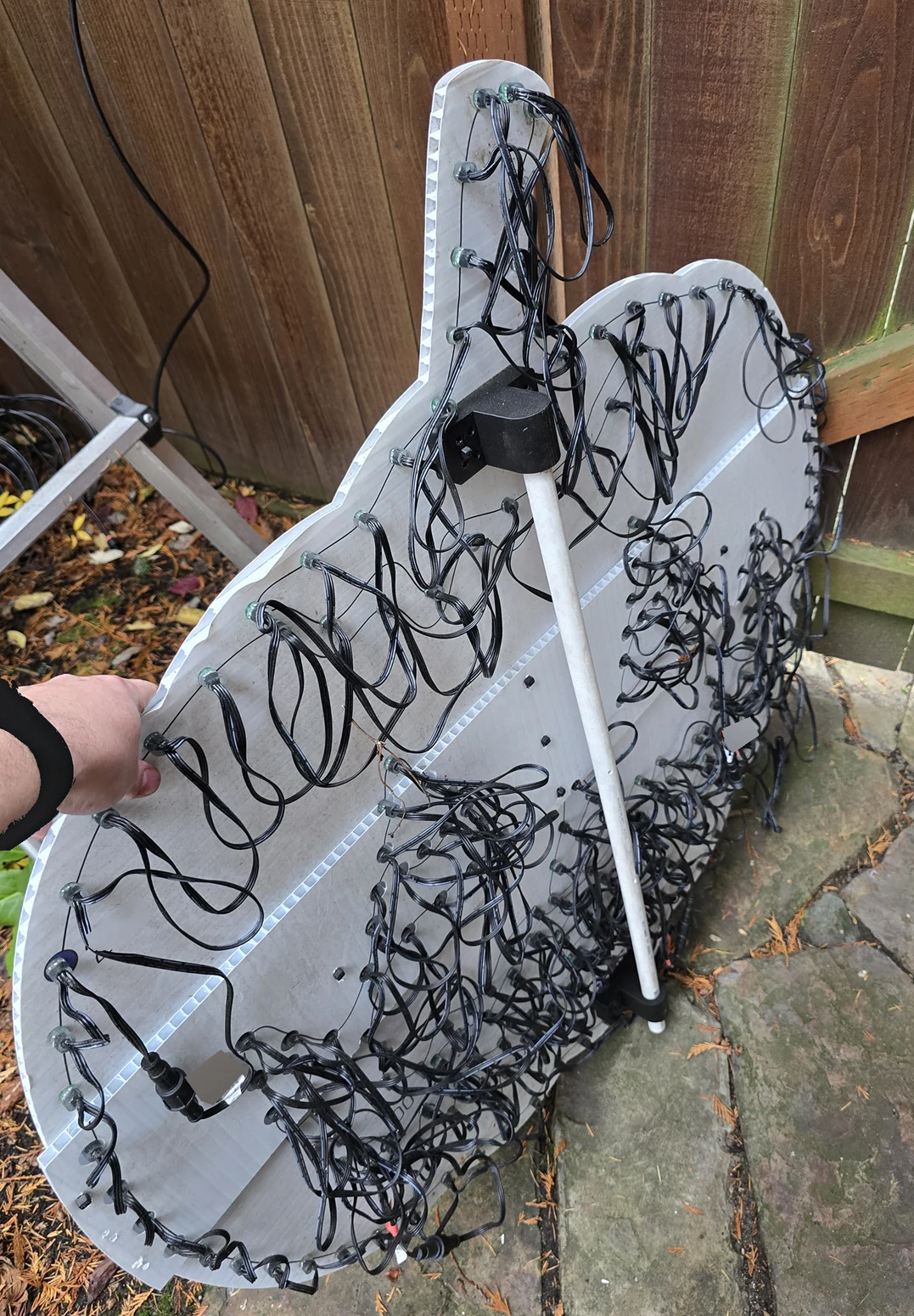
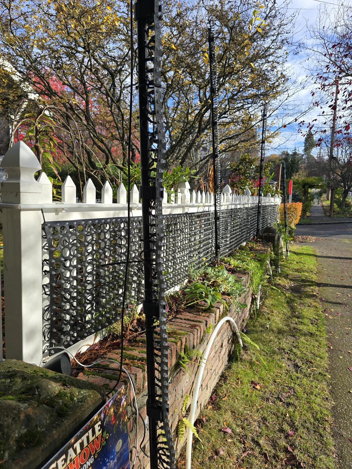
I only want to drill a hole in the house once. I made a small base that stays screwed in place, so I can slide one light holder off and slip another onto the same spot. For singing faces like the pumpkin, a printed bracket on the back holds a piece of PVC pipe. The pipe snaps into clips on the house or fence, and the whole face comes down just as easily.

  • Small square mounting base for the slide-on light holders.
    Screw-on Slide Base

    One screw goes through the middle. The tapered sides guide the holder into place.

Exploded view of the actual printed holder and square mounting base. The base has a center screw hole. An arrow shows the holder sliding down over the base.
The holder slides down over the base. The inset shows where the screw goes.
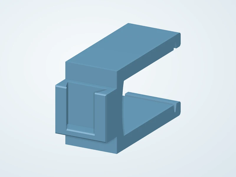
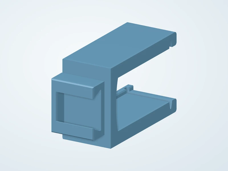
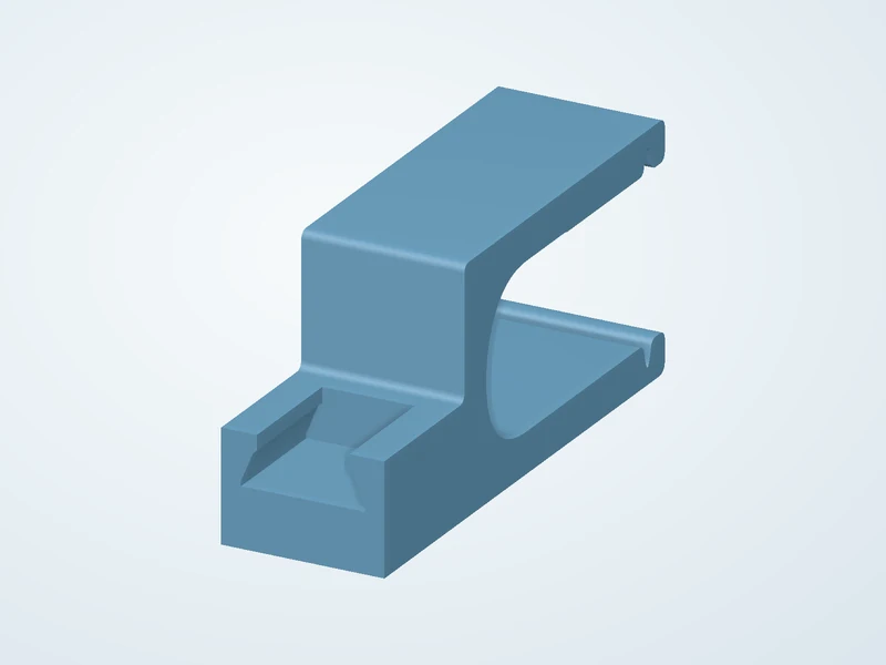
  • Rear view of a straight ribbon holder showing the tapered receiving slot.
    Straight Ribbon Light Holder

    I use this channel to keep the LED ribbon in place along a straight run.

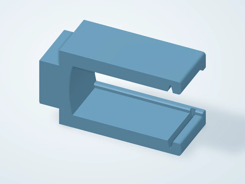
  • Open-sided ribbon holder with a raised rail inside the channel and a mounting block at the rear.
    Corner Ribbon Light Holder

    This one supports the ribbon where the run turns a corner.

  • Rear view of a corner ribbon holder with its tapered slot turned across the back.
    Alternate Corner Ribbon Light Holder

    I turned the slot the other way for corners that face a different direction.

  • The back of a long ribbon holder showing its tapered receiving slot.
    Horizontal Ribbon Light Holder

    This holder keeps the ribbon level along the house.

From the model to the house

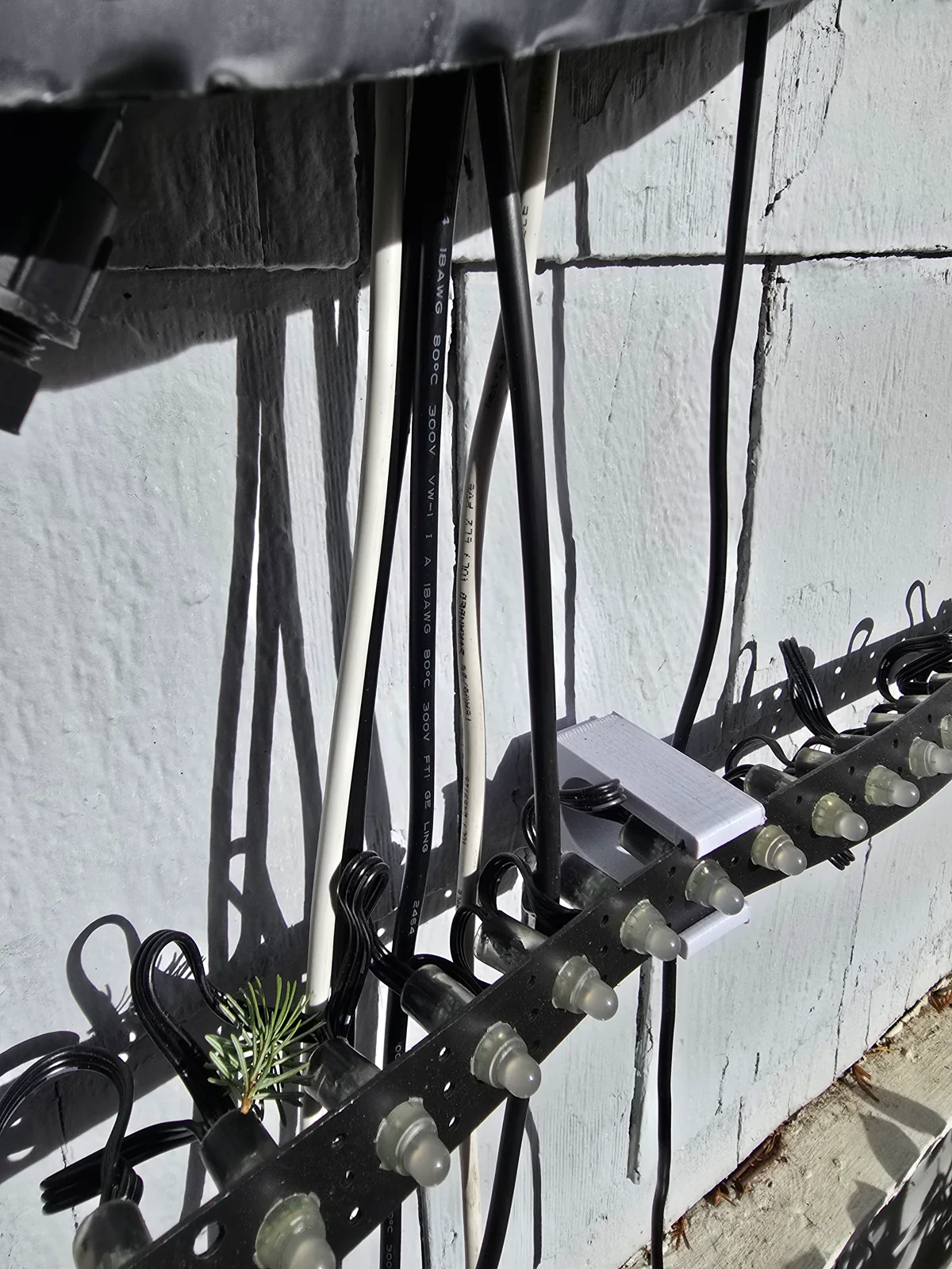
A pale printed holder fixed to the house supports a horizontal strip of wired pixel lights.
A printed holder supporting the lights on the house.
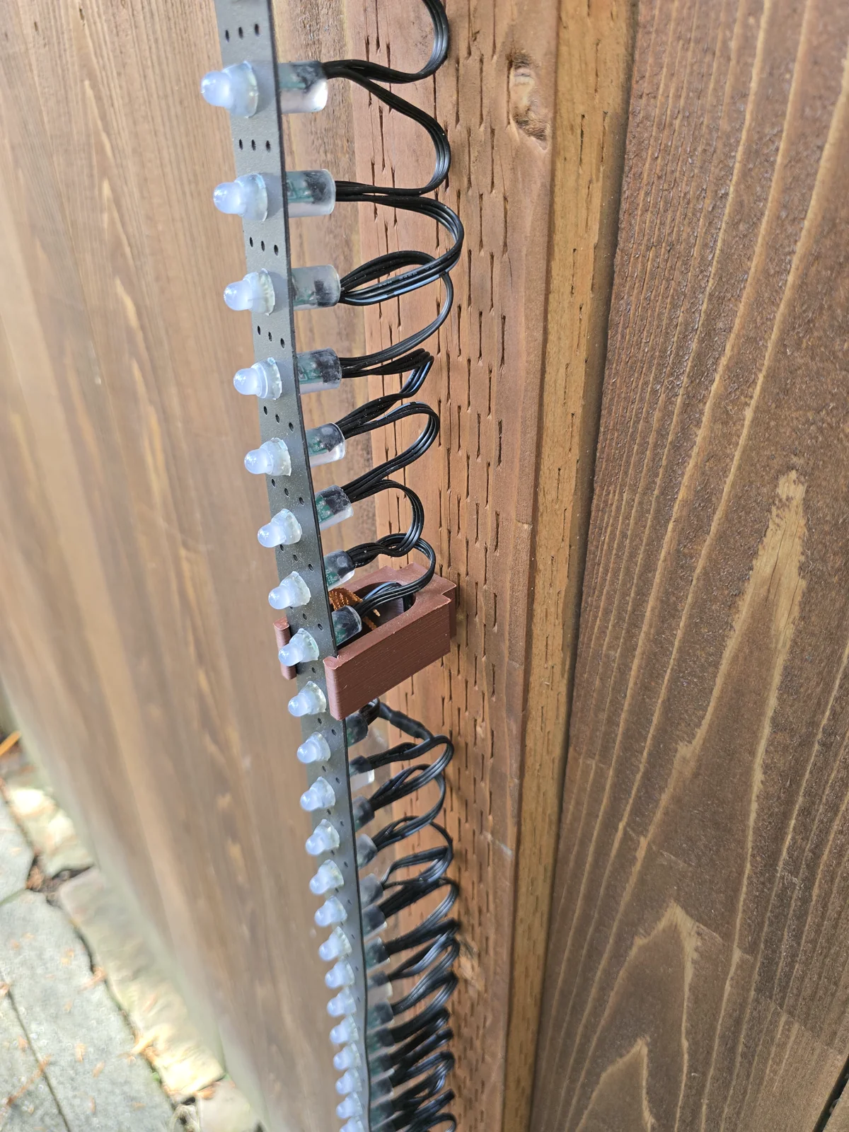
A brown printed holder on a wooden fence supports a vertical strip of pixel lights.
The same idea on the wood fence, with room behind the light strip for its wires.

A holder for one light

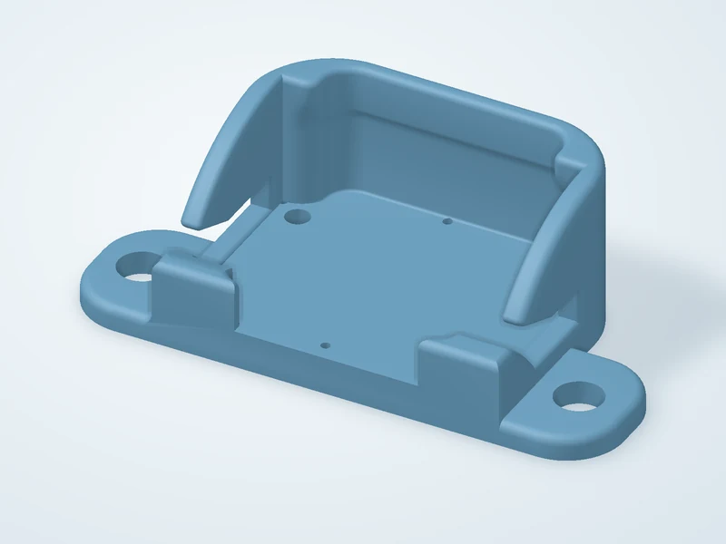
I made a little cradle for a single square LED module. The tabs are for mounting screws, and the cutouts give the wires room to pass through.

  • Open cradle with curved retaining arms and a round mounting hole on each side.
    Square LED Module Holder

    The sides keep one LED module seated while the wires pass through the openings.

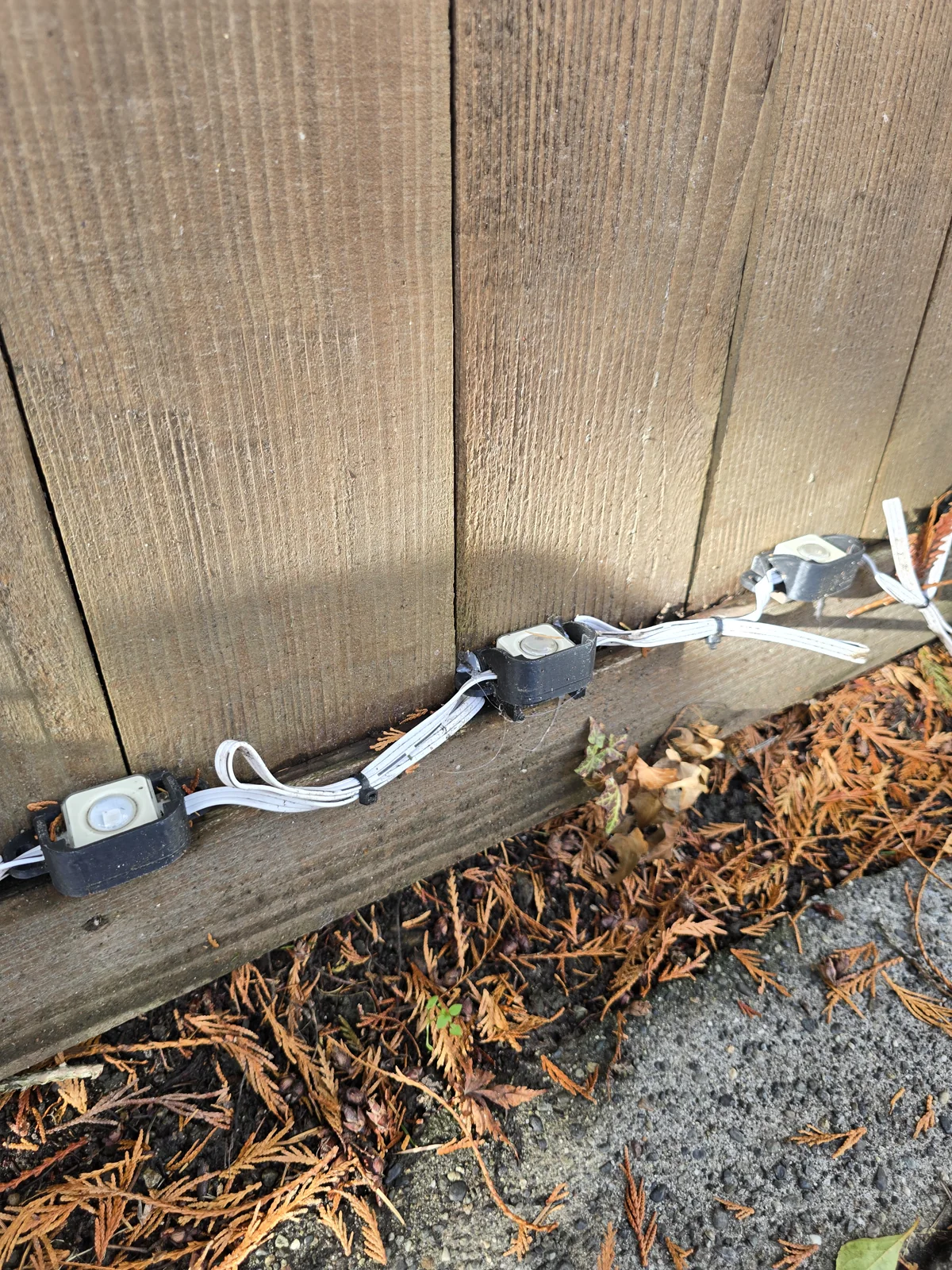
Square LED modules sit in dark printed cradles along the bottom of a wooden fence, joined by white wires.
The Square LED Module Holders installed along the fence.
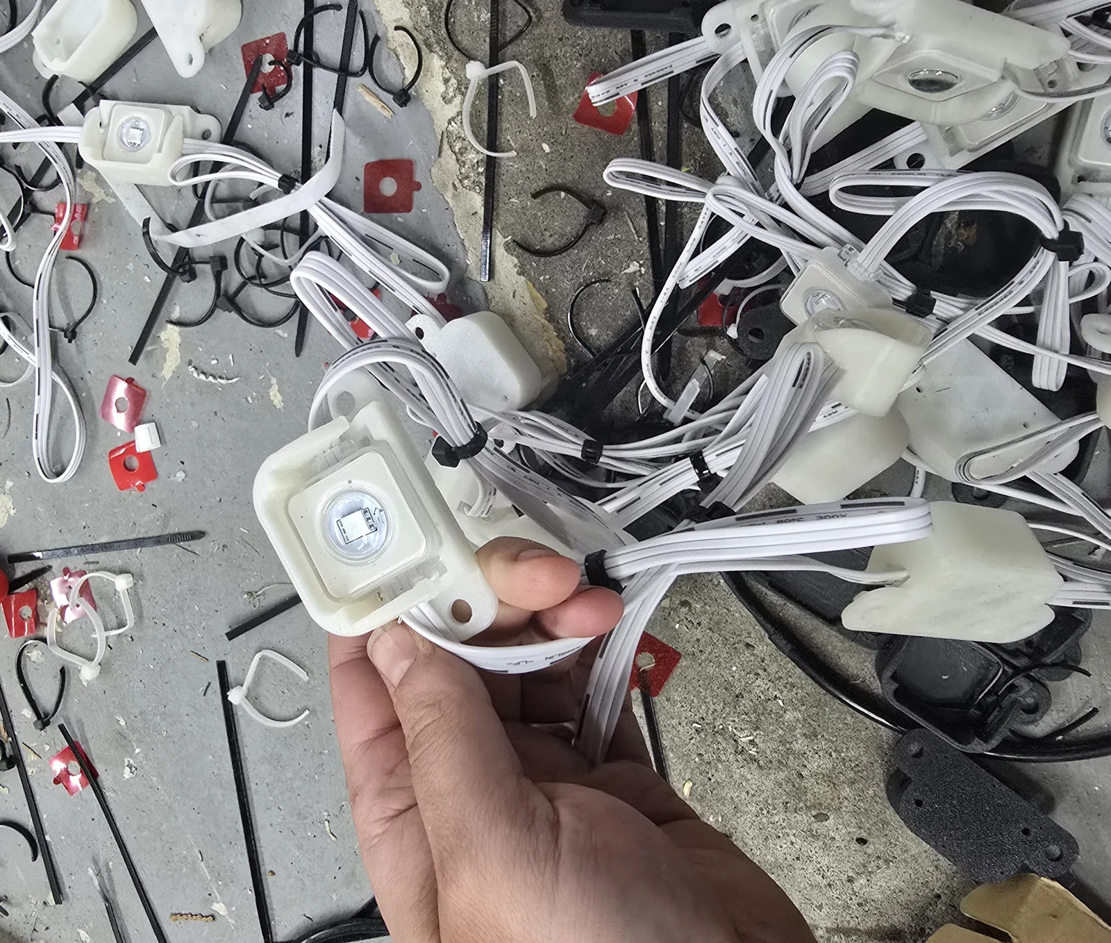
A hand holds a square LED module seated in a translucent printed cradle with white wires on either side.
The LED fits into the cradle with room for wires on either side.

What holds the yard props up

PVC, repurposed light poles, PEX tubing, and a few parts from the printer.

The PVC spiral

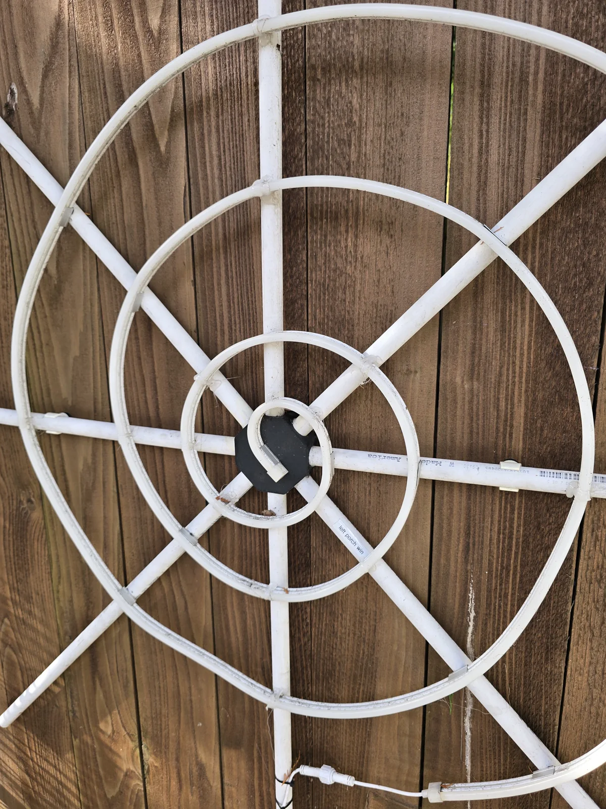
Eight white PVC spokes meet at a black printed hub behind a spiral of lights on the fence.
The Eight-Pole Holder in use at the center of the spiral.

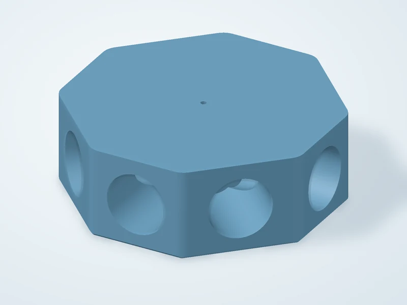
PVC spokes support the spiral, and the eight-socket hub I printed holds them together in the middle. The lights wind around that frame.

See the printed hub
  • Octagonal block with a circular pole socket on each side.
    Eight-Pole Holder

    Eight sockets hold the PVC spokes at the center of my spiral prop.

Repurposed light poles

Vertical LED ribbon strips held upright on repurposed outdoor light poles with printed brackets, beside the fence and PEX arches.
The vertical pole lights with the mounts I printed to hold the lights.

These started as poles made to go in the ground and hold up outdoor string or rope lights, like you'd use across a backyard. I reused just the poles and printed mounting brackets so they could hold the LED ribbon strips upright.

PEX arches

A white PEX tube forms a low arch in front of the brick wall and pixel fence.
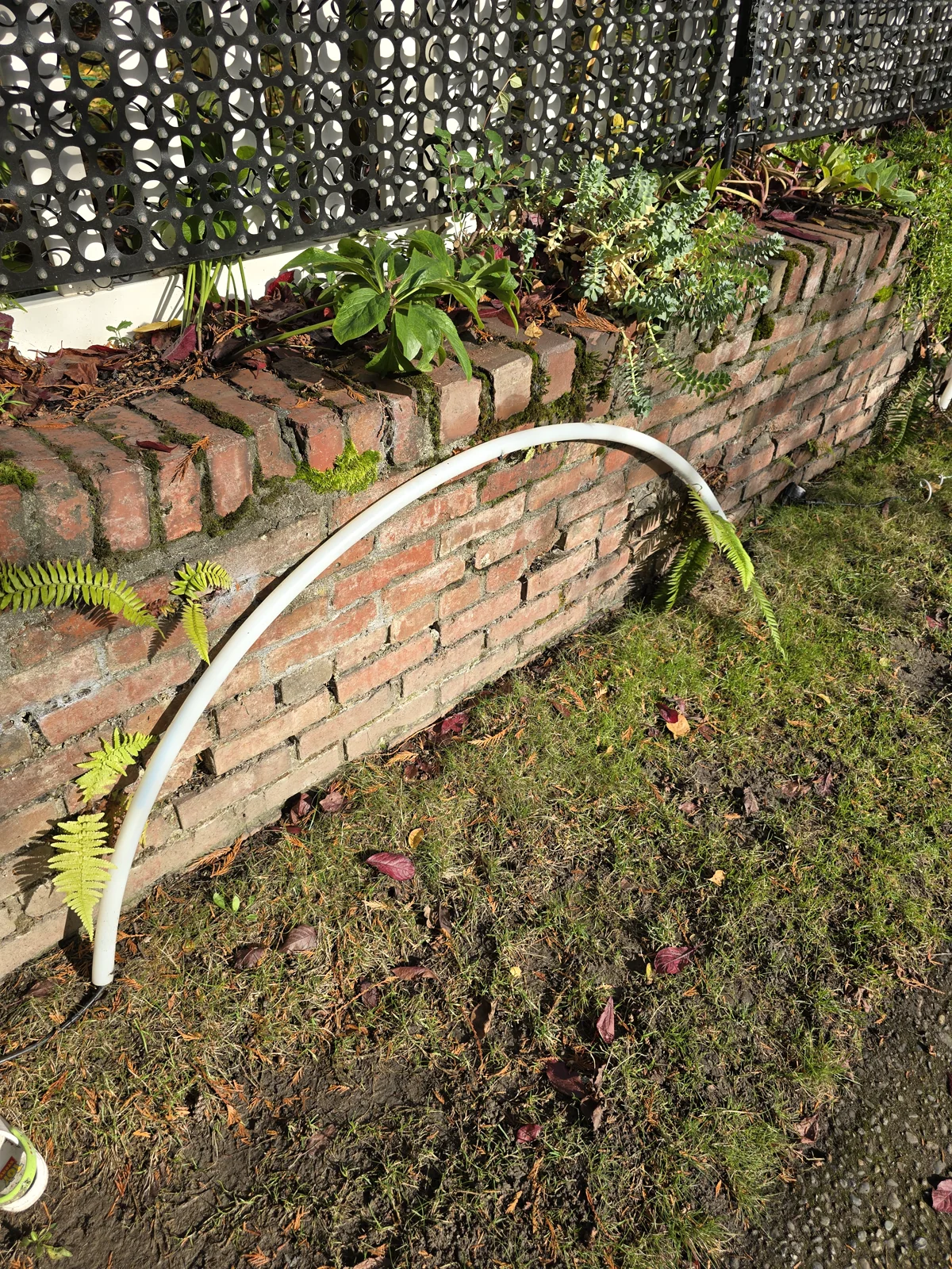
One of the arches with the lights off. The LED strip is inside the tube.

The arches are PEX tubes with an LED strip run through the inside. The tube gives each arch its shape and spreads the light along the curve.

Singing faces

Back of the white singing pumpkin with a white PVC mounting tube between the pixel wires.
The back of the singing pumpkin, with its mounting tube in place.

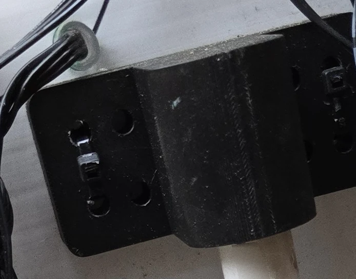
I use this same bracket on all my singing props.

See the bracket
The black printed bracket around the white tube on the back of the pumpkin.
The bracket stays on the prop when I unclip the tube.
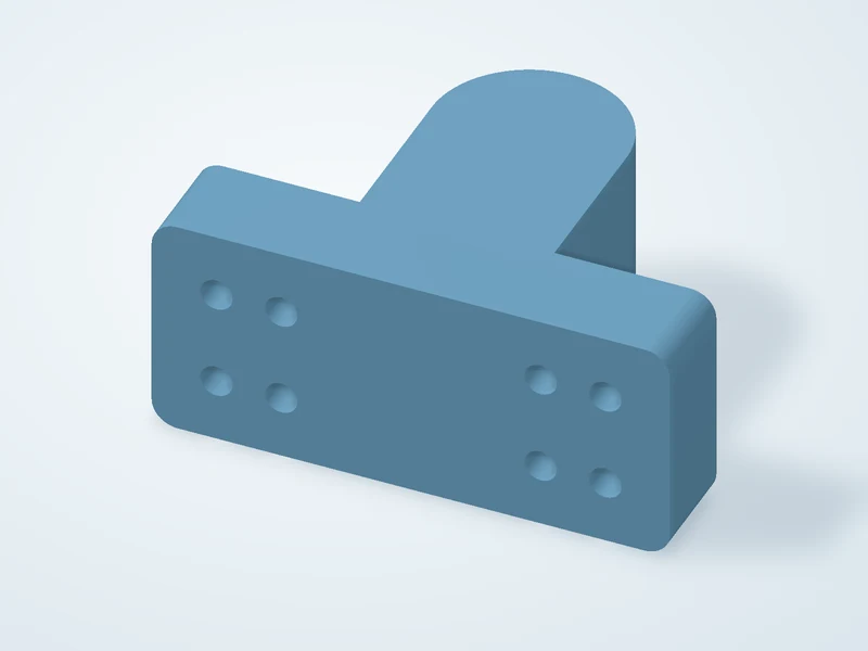
  • T-shaped bracket with a rounded center arm and eight holes across its mounting plate.
    Warlock Wide Perimeter Bracket

    The wide plate gives me several spots to fasten this bracket around the edge.

More printed parts

Fence and gutter mounts

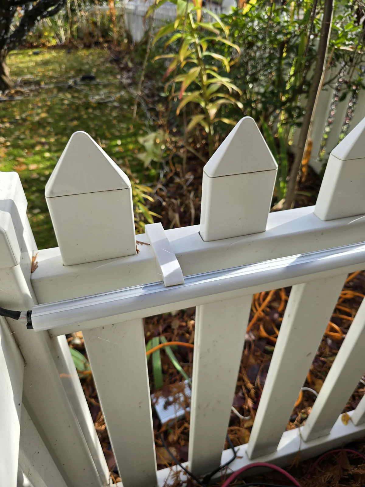
I shape each mount around what it needs to grab, like the top of the fence or the edge of a gutter. PVC also turns up in my fence supports. The photo shows the printed clip holding the light channel against the white fence.

A white printed clip hooks over a white fence rail and holds a light channel along its front edge.
The White Fence LED Channel Holder attached to the fence.
  • U-shaped fence bracket with two short retaining hooks on one side.
    White Fence LED Channel Holder

    I shaped the hooks to fit the white fence and keep the LED channel in place.

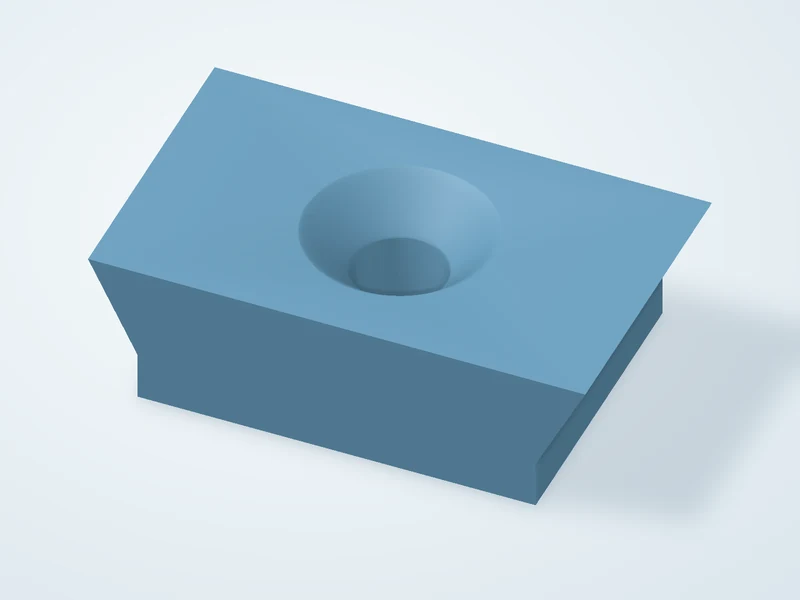
  • Short block with tapered sides and a single countersunk hole.
    ¾-Inch Wood Fence Mount

    The hole is recessed so the screw head can sit flush in the block.

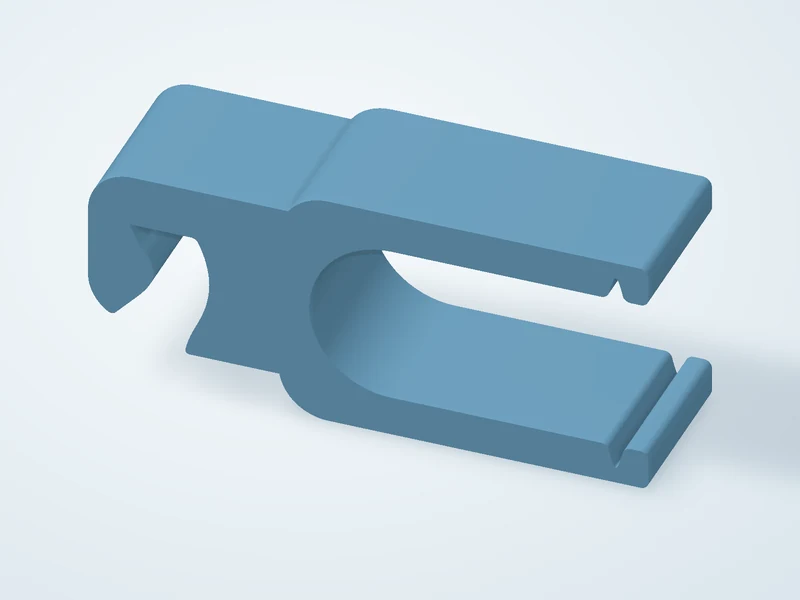
  • C-shaped ribbon clip with retaining lips and a curved gutter hook.
    Gutter LED Ribbon Holder

    One side hooks over the gutter. The other holds the ribbon.

Warlock prop mounts

I made several rings for the middle of the Warlock and brackets to hold it around the outside edge.

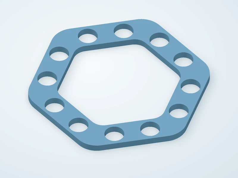
  • Thin hexagonal ring with a wide center opening and twelve round holes.
    Warlock Hexagonal Center Ring

    I kept this ring flat so it sits low around the center opening.

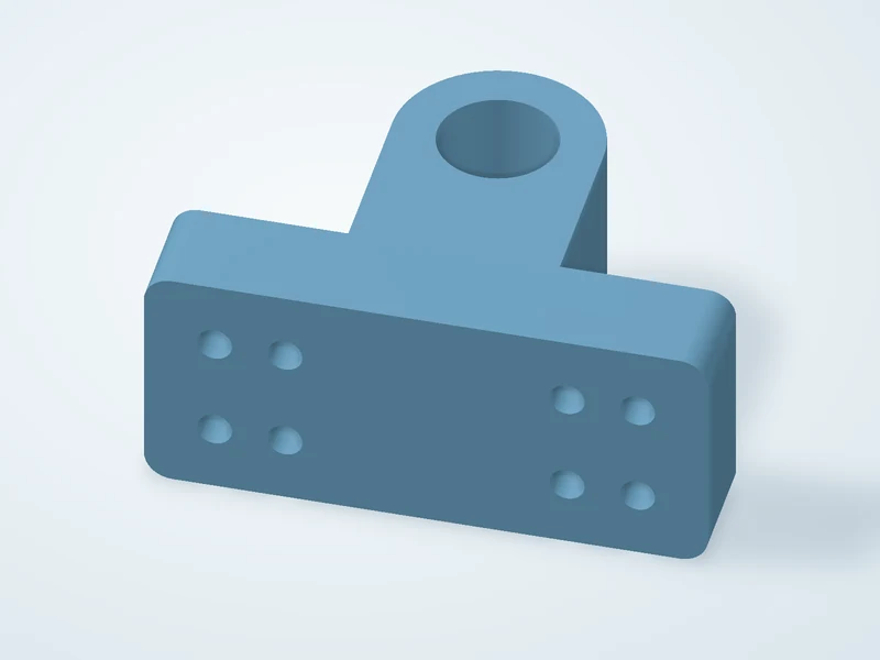
  • T-shaped bracket with a round opening in its arm and two sets of mounting holes.
    Warlock Open-Ended Perimeter Bracket

    I left an opening in the arm of this bracket for the outside edge.

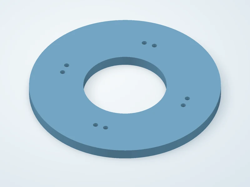
  • Flat circular ring with a large center opening and four pairs of small holes.
    Warlock Rear Center Ring

    This flat ring sits behind the center of the Warlock.

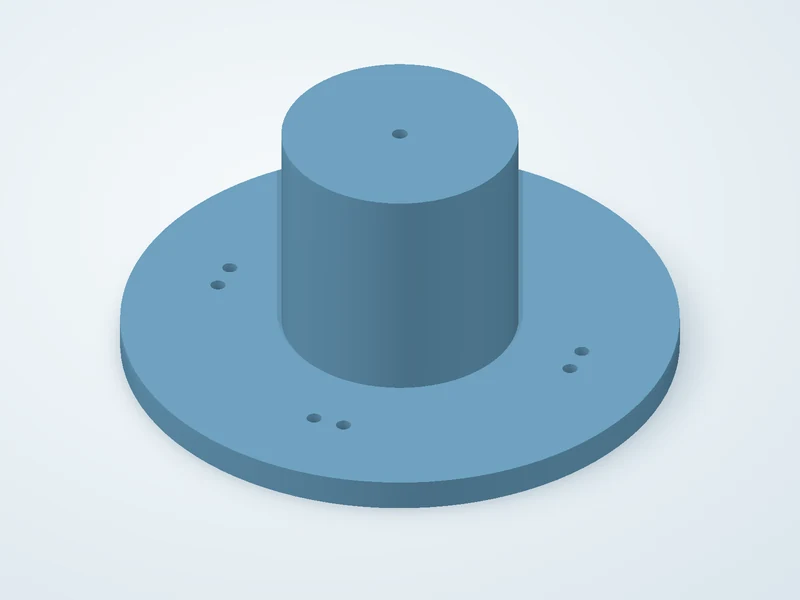
  • Round base with small mounting holes and a raised cylinder with a center hole.
    Warlock Front Center Ring

    The raised rim goes around the center opening on the front.

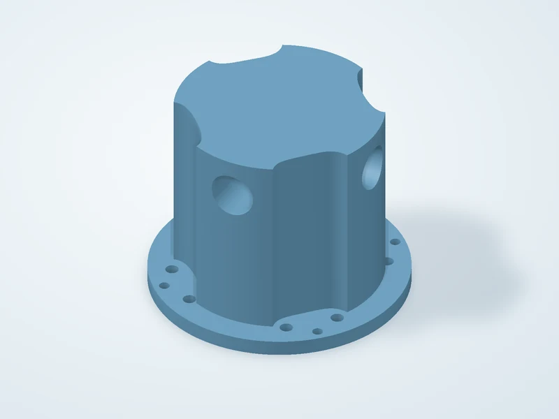
  • Tall scalloped hub with round side openings on a circular flange.
    Warlock Raised Center Hub

    This version raises the center while keeping the mounting holes around the base.

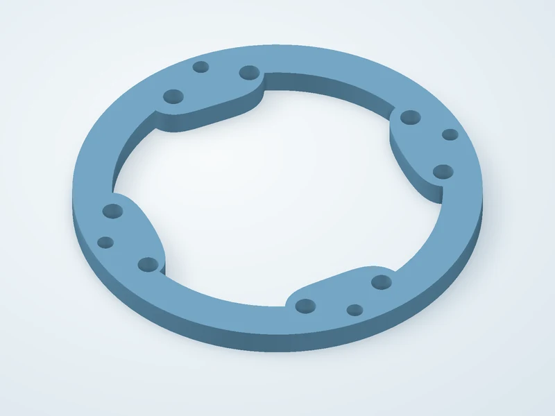
  • Open ring with four inward-facing tabs, each with three round holes.
    Warlock Center Ring Backing

    The tabs reach inward and give me places to fasten the backing.

  • Oval plate with paired mounting holes around a short raised cylinder.
    Warlock Oval Perimeter Mount

    The oval base puts fastening holes on either side of the raised post.

  • T-shaped bracket with a rounded center arm and eight holes across its mounting plate.
    Warlock Wide Perimeter Bracket

    The wide plate gives me several spots to fasten this bracket around the edge.

Want to print one of these? Send me the part name.

Request an STL
The show by the numbers

The show by the numbers

Show wire

5,600 ft

About 9¼ Space Needles tall.

Soldering

720 joints

240 pigtails, 3 wires each. I solder and heat-shrink every joint by hand.